
Table of Contents
Archer C64/A64 2.0 Product and Installation Guide
About This Guide
This guide is a complement of Quick Installation Guide. The Quick Installation Guide instructs you on quick internet setup, while this guide introduces the appearance, LEDs, buttons and ports of your router, and provides methods to connect the hardware and connect to the internet in different modes.
Please note that the images and pathway descriptions in this guide may differ from your actual product and firmware version.
Conventions
In this guide the following conventions are used:
|
Convention |
Description |
|---|---|
|
Underline |
Underlined words or phrases are hyperlinks. You can click to redirect to a website or a specific section. |
|
Bold |
Contents to be emphasized and texts on the web page are in bold, including the menus, items, buttons and so on. |
|
> |
The menu structures to show the path to load the corresponding page. For example, Settings > System Tools > Firmware Upgrade means the Firmware Upgrade page is under the System Tools menu that is located in the Settings tab. |
|
Note: |
Ignoring this type of note might result in a malfunction or damage to the device. |
|
Tip: |
Indicates important information that helps you make better use of your device. |
More Info
The latest software, management app and utility can be found at Download Center at https://www.tp-link.com/support/download.
The Quick Installation Guide can be found where you find this guide or inside the package.
Specifications can be found on the product page at https://www.tp-link.com.
TP-Link Community is provided for you to discuss our products and share knowledge at https://community.tp-link.com.
Our Technical Support contact information can be found at the Contact Technical Support page at https://www.tp-link.com/support.
Get to Know About Your Router
This chapter introduces what the router can do and its appearance.
It contains the following sections:
- Product Overview
- Appearance
1. Product Overview
The TP-Link router is designed to fully meet the need of Small Office/Home Office (SOHO) networks and users demanding higher networking performance. The powerful antennas ensure continuous Wi-Fi signal to all your devices while boosting widespread coverage throughout your home, and the built-in Ethernet ports supply high-speed connection to your wired devices.
Moreover, it is simple and convenient to set up and use the TP-Link router due to its intuitive web interface and the powerful Tether app.
2. Appearance
Front Panel
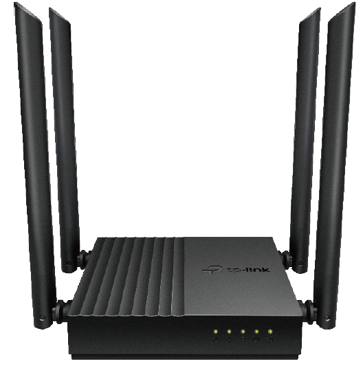
LED Explanation
You can check the router's working status by following the LED Explanation table.
|
Name |
Status |
Indication |
|
(Power) |
On |
The system has started up successfully. |
|
Blinking slowly |
The system is starting up or firmware upgrade is in progress. |
|
|
Blinking quickly |
WPS connection is in progress. |
|
|
(2.4GHz Wireless) |
On |
The 2.4GHz wireless band is enabled. |
|
Off |
The 2.4GHz wireless band is disabled. |
|
|
(5GHz Wireless) |
On |
The 5GHz wireless band is enabled. |
|
Off |
The 5GHz wireless band is disabled. |
|
|
(LAN) |
Green On |
At least one LAN port is connected. |
|
(Internet) |
Orange On |
The WAN port is connected, but internet is not available. |
|
Green On |
Internet is available. |


Back Panel
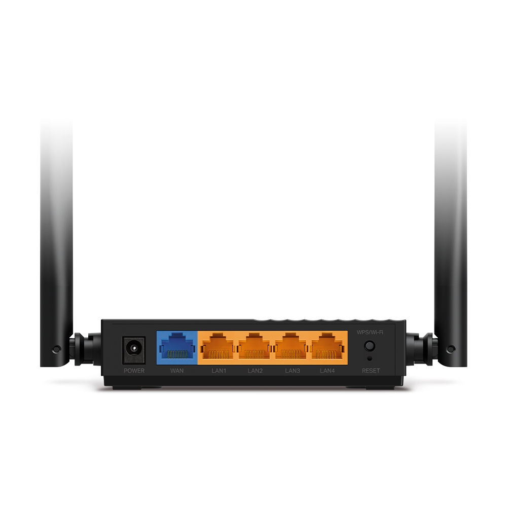
Button and Port Description
|
Button and Port |
Description |
|
Power Port |
For connecting the router to a power socket via the provided power adapter. |
|
WAN Port |
For connecting to a DSL/Cable modem, or an Ethernet port. |
|
LAN Ports (1/2/3/4) |
For connecting your PCs or other wired network devices to the router. |
|
WPS/Wi-Fi Button |
Press for 1 second to enable the WPS function. |
|
RESET Button |
Press and hold for more than 2 seconds to reset the router to its factory default settings. |
Connect the Hardware
This chapter contains the following sections:
• Position Your Router
• Connect Your Router
Position Your Router
With the router, you can access your network from anywhere within the wireless network coverage. However, the wireless signal strength and coverage vary depending on the actual environment of your router. Many obstacles may limit the range of the wireless signal, for example, concrete structures or thick walls.
For your security and best Wi-Fi performance, please:
• The product should not be located in a place where it will be exposed to moisture or excessive heat.
• Place the router in a location where it can be connected to multiple devices as well as to a power source.
• Make sure the cables and power cord are safely placed out of the way so they do not create a tripping hazard.
• The router can be placed on a shelf or desktop.
• Keep the router away from devices with strong electromagnetic interference, such as Bluetooth devices, cordless phones and microwaves.
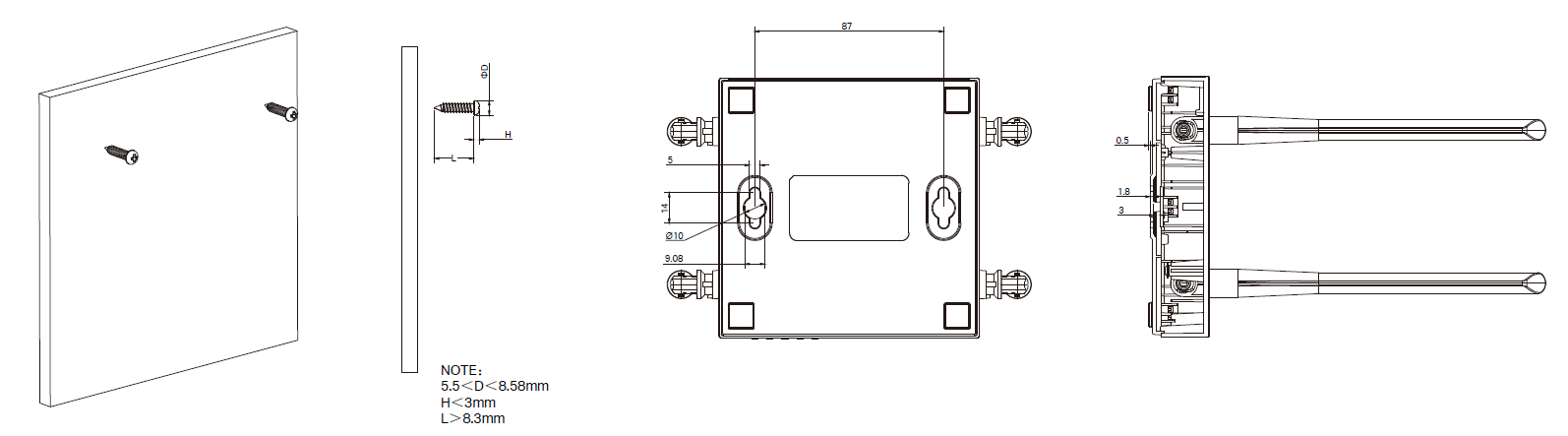
Note:
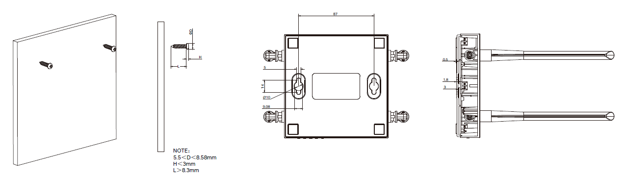
The diameter of the screw, 5.5 mm<D<8.58mm. The distance of two screws is 87 mm. The screw that project from the wall need around 3 mm based, and the length of the screw need to be at least 8.3 mm to withstand the weight of the product.
Connect Your Router
The Router provides four working modes: Wireless Router, WISP, Range Extender andAccess Point. You can choose the mode to better suit your network needs and follow the guide to complete the configuration.
Wireless Router Mode
Step 1. Follow the steps below to connect your router.
If your internet connection is through an Ethernet cable from the wall instead of through a DSL / Cable / Satellite modem, connect the Ethernet cable directly to the router’s WAN port, and then follow Step 4 and 5 to complete the hardware connection.
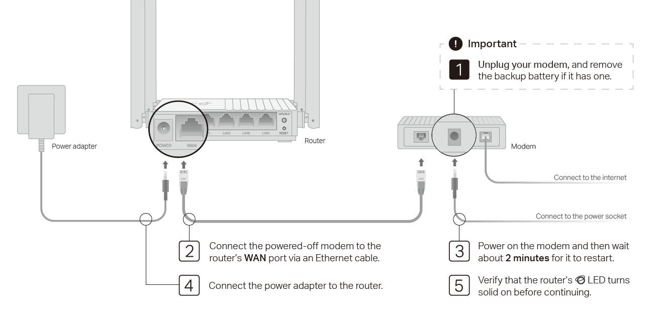
1 ) Turn off the modem, and remove the backup battery if it has one.
2 ) Connect the modem to the router’s WAN port with an Ethernet cable.
3 ) Turn on the modem, and then wait about 2 minutes for it to restart.
4 ) Connect the power adapter to the router.
5) Verify that the router’s  Internet LED turns solid on before continuing.
Step 2. Set up the Internet
Method 1. Set up the Internet Via TP-Link Tether App
The Tether app runs on iOS and Android devices, such as smartphones and tablets.
1. Launch the Apple App Store or Google Play store and search “TP-Link Tether” or simply scan the QR code to download and install the app.
2. Launch the Tether app and log in with your TP-Link ID. If you don’t have a TP-Link ID, create one first.
3. Tap the + button, and select Add a Router. Follow the steps to complete the setup and connect to the internet.
Note: Due to Tether app updates, your actual user interface and pathway may differ from those described here.
4. Connect your devices to the newly configured wireless networks of the router and enjoy the internet!
Method 2. Set up the Internet Via Web Management Page
1. Connect your computer or wireless devices to the router.
• Wired
Turn off the Wi-Fi on your computer and connect the devices to the LAN port of yourrouter.
• Wirelessly
1 ) Find the SSIDs (Network Names) and Wireless Password printed on the label at the bottom of the router.
2 ) Click the network icon of your computer or go to Wi-Fi Settings of your smart device, and then select the SSID to join the network.
• Use the WPS button
Wireless devices that support WPS, including Android phones, tablets, most USB network cards, can be connected to your router through this method.
Note:
• WPS is not supported by iOS devices.
• The WPS function cannot be configured if the wireless function of the router is disabled. Also, the WPS function will be disabled if your wireless encryption is WEP. Please make sure the wireless function is enabled and is configured with the appropriate encryption before configuring the WPS.
1 ) Tab the WPS icon on the device’s screen. Here we take an Android phone as an example.
2 ) Immediately press the WPS button on your router.
2. Enter http://tplinkwifi.net in the address bar of a web browser and Login.
3. Go through the quick setup process and select Wireless Router.
4. Enjoy! For wireless devices, you may have to reconnect to the wireless network if you have customized the SSID (wireless name) and password during the configuration.
Access Point Mode
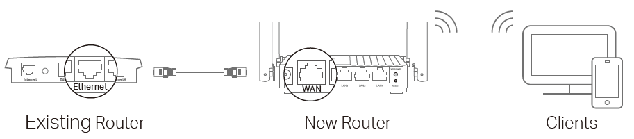
If you already have a router, you can switch this new router to Access Point mode to extend your existing network. Follow the asteps below.
1. Power on the router.
2. Connect the router's WAN port to your existing router’s Ethernet port via an Ethernet cable as shown above.
3. Connect a computer to the router via an Ethernet cable or wirelessly by using the SSID (network name) and Wireless Password printed on the label at the bottom of the router.
4. Launch a web browser and enter http://tplinkwifi.net in the address bar. Create a password to log in.
5. Run the Quick Setup, click Change Mode in the top right corner then select Access Point Mode. Note: You can also go to Advanced > System > Operation Mode to switch to Access Point Mode.
6. Wait for the router to reboot, then log in and follow the Quick Setup to complete the setup.
Authentication
For EU Version, use only power supplies listed in the user instructions:
|
Manufacturer |
Model |
|---|---|
|
TP-Link |
T090085-2C1 T090085-2D1 T090085-2E1 |
FCC compliance information statement

Product Name: AC1200 MU-MIMO Wi-Fi Router
Model Number: Archer C64/Archer A64
| Component Name | Model |
|---|---|
| I.T.E. Power Supply | T120100-2B1 |
Responsible party:
TP-Link Systems Inc.
Address: 10 Mauchly, Irvine, CA 92618
Website: http://www.tp-link.com/us/
Tel: +1 626 333 0234
Fax: +1 909 527 6804
E-mail: sales.usa@tp-link.com
This equipment has been tested and found to comply with the limits for a Class B digital device, pursuant to part 15 of the FCC Rules. These limits are designed to provide reasonable protection against harmful interference in a residential installation. This equipment generates, uses and can radiate radio frequency energy and, if not installed and used in accordance with the instructions, may cause harmful interference to radio communications. However, there is no guarantee that interference will not occur in a particular installation. If this equipment does cause harmful interference to radio or television reception, which can be determined by turning the equipment off and on, the user is encouraged to try to correct the interference by one or more of the following measures:
• Reorient or relocate the receiving antenna.
• Increase the separation between the equipment and receiver.
• Connect the equipment into an outlet on a circuit different from that to which the receiver is connected.
• Consult the dealer or an experienced radio/ TV technician for help.
This device complies with part 15 of the FCC Rules. Operation is subject to the following two conditions:
1. This device may not cause harmful interference.
2. This device must accept any interference received, including interference that may cause undesired operation.
Any changes or modifications not expressly approved by the party responsible for compliance could void the user’s authority to operate the equipment.
Note: The manufacturer is not responsible for any radio or TV interference caused by unauthorized modifications to this equipment. Such modifications could void the user’s authority to operate the equipment.
FCC RF Radiation Exposure Statement
This equipment complies with FCC RF radiation exposure limits set forth for an uncontrolled environment. This device and its antenna must not be co-located or operating in conjunction with any other antenna or transmitter.
To comply with FCC RF exposure compliance requirements, this grant is applicable to only Mobile Configurations. The antennas used for this transmitter must be installed to provide a separation distance of at least 20 cm from all persons and must not be co-located or operating in conjunction with any other antenna or transmitter.
FCC compliance information statement
Product Name: I.T.E. Power Supply
Model Number: T120100-2B1
Responsible party:
TP-Link Systems Inc.
Address: 10 Mauchly, Irvine, CA 92618
Website: http://www.tp-link.com/us/
Tel: +1 626 333 0234
Fax: +1 909 527 6804
E-mail: sales.usa@tp-link.com
This equipment has been tested and found to comply with the limits for a Class B digital device, pursuant to part 15 of the FCC Rules. These limits are designed to provide reasonable protection against harmful interference in a residential installation. This equipment generates, uses and can radiate radio frequency energy and, if not installed and used in accordance with the instructions, may cause harmful interference to radio communications. However, there is no guarantee that interference will not occur in a particular installation. If this equipment does cause harmful interference to radio or television reception, which can be determined by turning the equipment off and on, the user is encouraged to try to correct the interference by one or more of the following measures:
Reorient or relocate the receiving antenna.
Increase the separation between the equipment and receiver.
Connect the equipment into an outlet on a circuit different from that to which the receiver is connected.
Consult the dealer or an experienced radio/ TV technician for help.
1. This device complies with part 15 of the FCC Rules. Operation is subject to the following two conditions:
2. This device may not cause harmful interference.
This device must accept any interference received, including interference that may cause undesired operation.
Any changes or modifications not expressly approved by the party responsible for compliance could void the user’s authority to operate the equipment.
We, TP-Link Systems Inc., has determined that the equipment shown as above has been shown to comply with the applicable technical standards, FCC part 15. There is no unauthorized change is made in the equipment and the equipment is properly maintained and operated.
Issue Date: 2025-09-29
CE Mark Warning

OPERATING FREQUENCY(the maximum transmitted power)
2400 MHz -2483.5 MHz (20dBm)
5150 MHz -5250 MHz (23dBm)
EU Declaration of Conformity
TP-Link hereby declares that the device is in compliance with the essential requirements and other relevant provisions of directives 2014/53/EU, 2009/125/EC, 2011/65/EU and (EU)2015/863.
The original EU Declaration of Conformity may be found at https://www.tp-link.com/en/support/ce/
RF Exposure Information
This device meets the EU requirements (2014/53/EU Article 3.1a) on the limitation of exposure of the general public to electromagnetic fields by way of health protection.
The device complies with RF specifications when the device used at 20 cm from your body.
National Restrictions
Frequency band: 5150 - 5250 MHz:
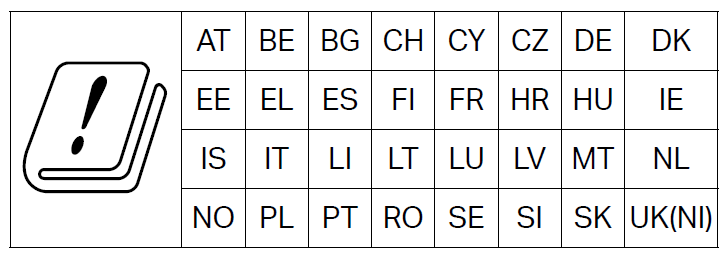
Indoor use: Inside buildings only. Installations and use inside road vehicles and train carriages are not permitted. Limited outdoor use: If used outdoors, equipment shall not be attached to a fixed installation or to the external body of road vehicles, a fixed infrastructure or a fixed outdoor antenna. Use by unmanned aircraft systems (UAS) is limited to within the 5170 - 5250 MHz band.
UKCA Mark

UK Declaration of Conformity
TP-Link hereby declares that the device is in compliance with the essential requirements and other relevant provisions of the Radio Equipment Regulations 2017.
The original UK Declaration of Conformity may be found at https://www.tp-link.com/support/ukca
National Restrictions
Attention: This device may only be used indoors in Great Britain.
Canadian Compliance Statement
This device contains licence-exempt transmitter(s)/receiver(s) that comply with Innovation, Science and Economic Development Canada’s licence-exempt RSS(s). Operation is subject to the following two conditions:
1. This device may not cause interference.
2. This device must accept any interference, including interference that may cause undesired operation of the device.
L’émetteur/récepteur exempt de licence contenu dans le présent appareil est conforme aux CNR d’Innovation, Sciences et Développement économique Canada applicables aux appareils radio exempts de licence. L’exploitation est autorisée aux deux conditions suivantes :
1) L’appareil ne doit pas produire de brouillage;
2) L’appareil doit accepter tout brouillage radioélectrique subi, même si le brouillage est susceptible d’en compromettre le fonctionnement.
Caution:
The device for operation in the band 5150–5250 MHz is only for indoor use to reduce the potential for harmful interference to co-channel mobile satellite systems;
Avertissement:
Le dispositif fonctionnant dans la bande 5150-5250 MHz est réservé uniquement pour une utilisation à l’intérieur afin de réduire les risques de brouillage préjudiciable aux systèmes de satellites mobiles utilisant les mêmes canaux;
Radiation Exposure Statement:
This equipment complies with IC radiation exposure limits set forth for an uncontrolled environment. This equipment should be installed and operated with minimum distance 20cm between the radiator & your body.
Déclaration d’exposition aux radiations:
Cet équipement est conforme aux limites d’exposition aux rayonnements IC établies pour un environnement non contrôlé. Cet équipement doit être installé et utilisé avec un minimum de 20 cm de distance entre la source de rayonnement et votre corps.
Industry Canada Statement
CAN ICES-003 (B)/NMB-003(B)
Korea Warning Statements
당해 무선설비는 운용중 전파혼신 가능성이 있음.
NCC Notice & BSMI Notice
注意!
取得審驗證明之低功率射頻器材,非經核准,公司、商號或使用者均不得擅自變更頻率、加大功率或變更原設計之特性及功能。
低功率射頻器材之使用不得影響飛航安全及干擾合法通信;經發現有干擾現象時,應立即停用,並改善至無干擾時方得繼續使用。
前述合法通信,指依電信管理法規定作業之無線電通信。
低功率射頻器材須忍受合法通信或工業、科學及醫療用電波輻射性電機設備之干擾。
應避免影響附近雷達系統之操作。
高增益指向性天線只得應用於固定式點對點系統。
安全諮詢及注意事項
• 請使用原裝電源供應器或只能按照本產品注明的電源類型使用本產品。
• 清潔本產品之前請先拔掉電源線。請勿使用液體、噴霧清潔劑或濕布進行清潔。
• 注意防潮,請勿將水或其他液體潑灑到本產品上。
• 插槽與開口供通風使用,以確保本產品的操作可靠並防止過熱,請勿堵塞或覆蓋開口。
• 請勿將本產品置放於靠近熱源的地方。除非有正常的通風,否則不可放在密閉位置中。
• 不要私自拆開機殼或自行維修,如產品有故障請與原廠或代理商聯繫。
• 運作溫度: 0°C~40°C (32°F~104°F)
• 適配器應安裝在設備附近,並應易於接近。
• 請使用製造商提供的電源適配器。如果您有任何問題,請隨時與我們聯繫。
限用物質含有情況標示聲明書
| 設備名稱:AC1200 MU-MIMO Wi-Fi Router 型號(型式):Archer C64/Archer A64 Equipment name Type designation (Type) |
||||||
|---|---|---|---|---|---|---|
| 單元 Unit |
限用物質及其化學符號 Restricted substances and its chemical symbols |
|||||
| 鉛 Lead (Pb) |
汞 Mercury (Hg) |
鎘 Cadmium (Cd) |
六價鉻 Hexavalent chromium (Cr+6) |
多溴聯苯 Polybrominated biphenyls (PBB) |
多溴二苯醚 Polybrominated diphenyl ethers (PBDE) |
|
| PCB | ○ | ○ | ○ | ○ | ○ | ○ |
| 外殼 | ○ | ○ | ○ | ○ | ○ | ○ |
| 電源供應器 | − | ○ | ○ | ○ | ○ | ○ |
| 其他及其配件 | ○ | ○ | ○ | ○ | ○ | ○ |
| 備考1.〝超出0.1 wt %〞及〝超出0.01 wt %〞係指限用物質之百分比含量超出百分比含量基準值 Note 1:“Exceeding 0.1 wt %” and “exceeding 0.01 wt %” indicate that the percentage content of the restricted substance exceeds the reference percentage value of presence condition. 備考2.〝○〞係指該項限用物質之百分比含量未超出百分比含量基準值。 Note 2:“○” indicates that the percentage content of the restricted substance does not exceed the percentage of reference value of presence. 備考3.〝-〞係指該項限用物質為排除項目。 Note 3:The “−” indicates that the restricted substance corresponds to the exemption. |
||||||

Продукт сертифіковано згідно с правилами системи УкрСЕПРО на відповідність вимогам нормативних документів та вимогам, що передбачені чинними законодавчими актами України.

Safety Information
Keep the device away from water, fire, humidity or hot environments.
Do not attempt to disassemble, repair, or modify the device. If you need service, please contact us.
Do not use damaged charger or USB cable to charge the device.
Do not use any other chargers than those recommended.
Do not use the device where wireless devices are not allowed.
Adapter shall be installed near the equipment and shall be easily accessible.
Use only power supplies which are provided by manufacturer and in the original packing of this product. If you have any questions, please don’t hesitate to contact us.
Operating Temperature: 0℃ ~ 40℃ (32℉ ~ 104℉)
This product uses radios and other components that emit electromagnetic fields. Electromagnetic fields and magnets may interfere with pacemakers and other implanted medical devices. Always keep the product and its power adapter more than 15 cm (6 inches) away from any pacemakers or other implanted medical devices. If you suspect your product is interfering with your pacemaker or any other implanted medical device, turn off your product and consult your physician for information specific to your medical device.
Please read and follow the above safety information when operating the device. We cannot guarantee that no accidents or damage will occur due to improper use of the device. Please use this product with care and operate at your own risk.
Explanation of the symbols on the product label
Note: The product label is on the bottom of the product and its power supply. Symbols may vary from products.
注意:產品標籤可以在產品底部和其I.T.E.電源供應器上找到。符號可能因產品而異。
| Symbol 符號解釋 |
Explanation 解釋 |
|---|---|
 |
Class II equipment Class II 設備 |
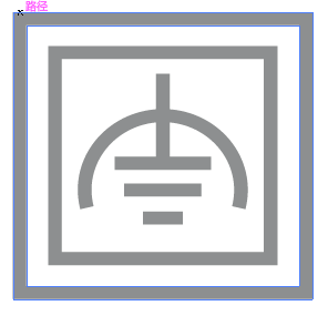 |
Class II equipment with functional earthing 具有功能接地的Class II 設備 |
 |
Alternating current 交流電 |
 |
DC voltage 直流電壓 |
 |
Polarity of output terminals 輸出端子極性 |
 |
Indoor use only 僅限室內使用 |
 |
Dangerous voltage 危險電壓 |
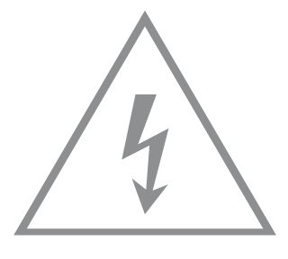 |
Caution, risk of electric shock 注意,有觸電危險 |
 |
Energy efficiency Marking 能源效率標示 |
 |
Protective earth 保護接地 |
 |
Earth 接地 |
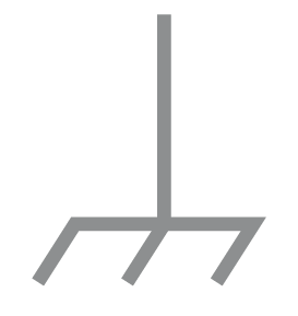 |
Frame or chassis 機架接地 |
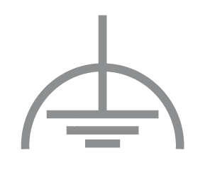 |
Functional earthing 功能接地 |
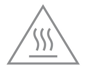 |
Caution, hot surface 警告,表面高溫 |
 |
Caution 警告 |
 |
Operator’s manual 操作手冊 |
 |
Stand-by 待機 |
 |
“ON”/”OFF” (push-push) 「開」/「關」 ( 按壓式) |
 |
Fuse 保險絲 |
 |
Fuse is used in neutral N 保險絲用於中性線N |
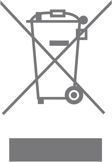 |
RECYCLING This product bears the selective sorting symbol for Waste electrical and electronic equipment (WEEE). This means that this product must be handled pursuant to European directive 2012/19/EU in order to be recycled or dismantled to minimize its impact on the environment. User has the choice to give his product to a competent recycling organization or to the retailer when he buys a new electrical or electronic equipment. 回收利用 本產品標示有「廢棄電氣電子設備(WEEE)」的分類回收標誌。這表示本產品必須依據歐盟指令 2012/19/EU 進行妥善回收或拆 解,以減少對環境的影響。 使用者可選擇將本產品交給合格的回收機構,或在購買新電器或電子設備時,交回給零售商進行回收處理。 |
 |
Caution, avoid listening at high volume levels for long periods 注意,避免長時間以高音量收聽 |
 |
Disconnection, all power plugs 斷開所有電源插頭 |
| m | Switch of mini-gap construction 微間隙結構的開關 |
| µ | Switch of micro-gap construction (for US version) Switch of micro-gap / micro-disconnection construction (for other versions except US) 微小間隙結構開關(適用於美國版) 微小間隙 / 微小斷開結構開關(適用於美國以外的其他版本) |
| ε | Switch without contact gap (Semiconductor switching device) 無接點間隙開關(半導體開關裝置) |
Appendix I
定位您的路由器:
產品不應放置在會受潮濕或過高溫度的地方。
將路由器放置在能夠連接多個設備並接上電源的地方。
請確保線和電源線放置在安全位置,以免造成絆倒的危險。
路由器可以放置在架子上或桌面上。
將路由器遠離具有強烈電磁干擾的設備,例如藍牙設備、無線電話和微波爐。
通常,路由器放置在水平的表面上,例如在架子上或桌面上。該設備還可以安裝在牆上,如下圖所示。
注意:
螺絲頭直徑為5.5mm<D<8.58mm,兩個螺絲之間的距離為87mm。從牆壁突出的螺絲需要約3mm的基底,並且螺絲的長度至少需8.3mm才能承受產品的重量。