
Table of Contents
5/8/16-Port Gigabit Easy Smart Switch_Installation Guide
Note: For simplicity, we will take TL-SG108PE for example throughout this Guide.
Installation
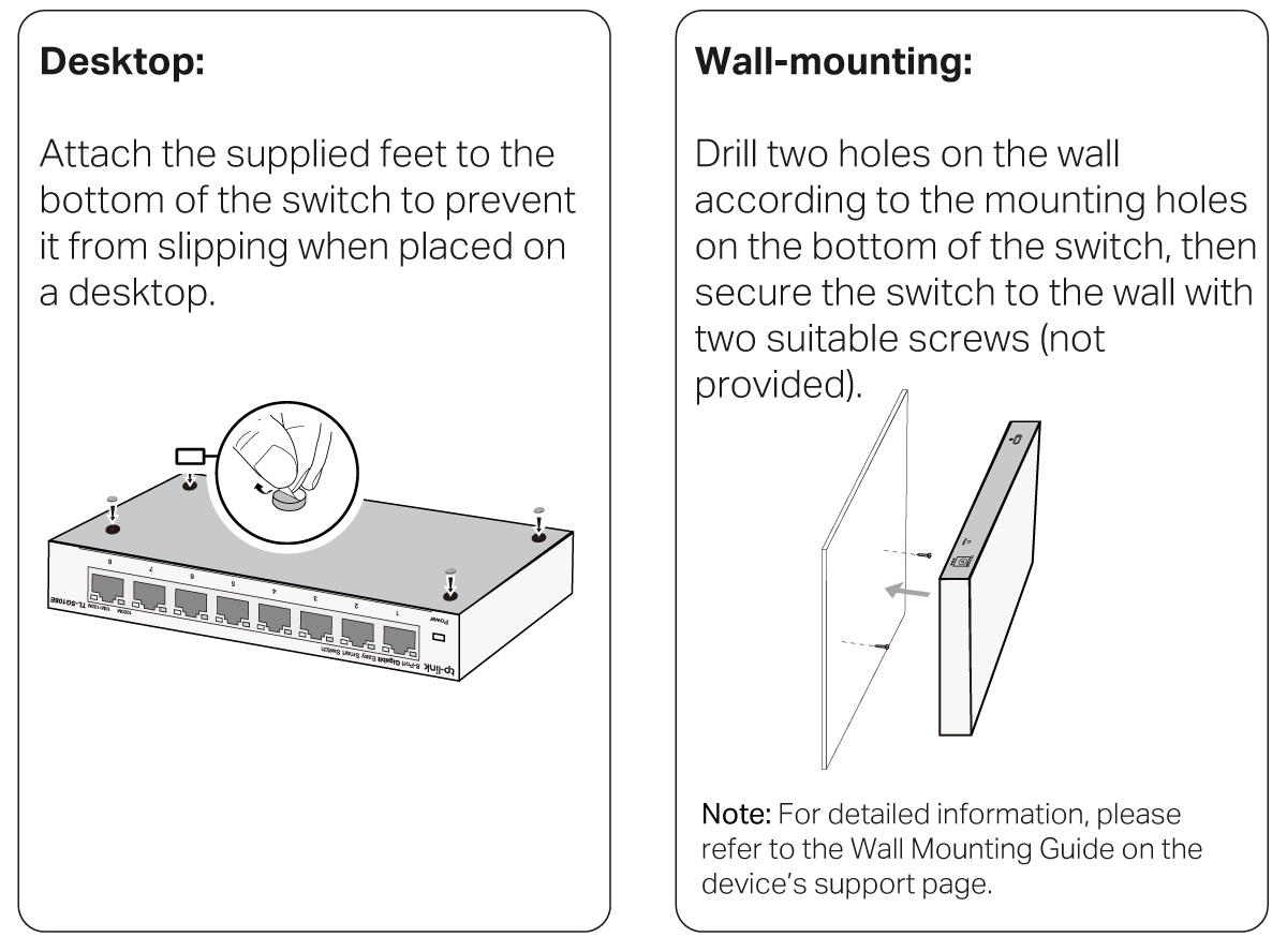
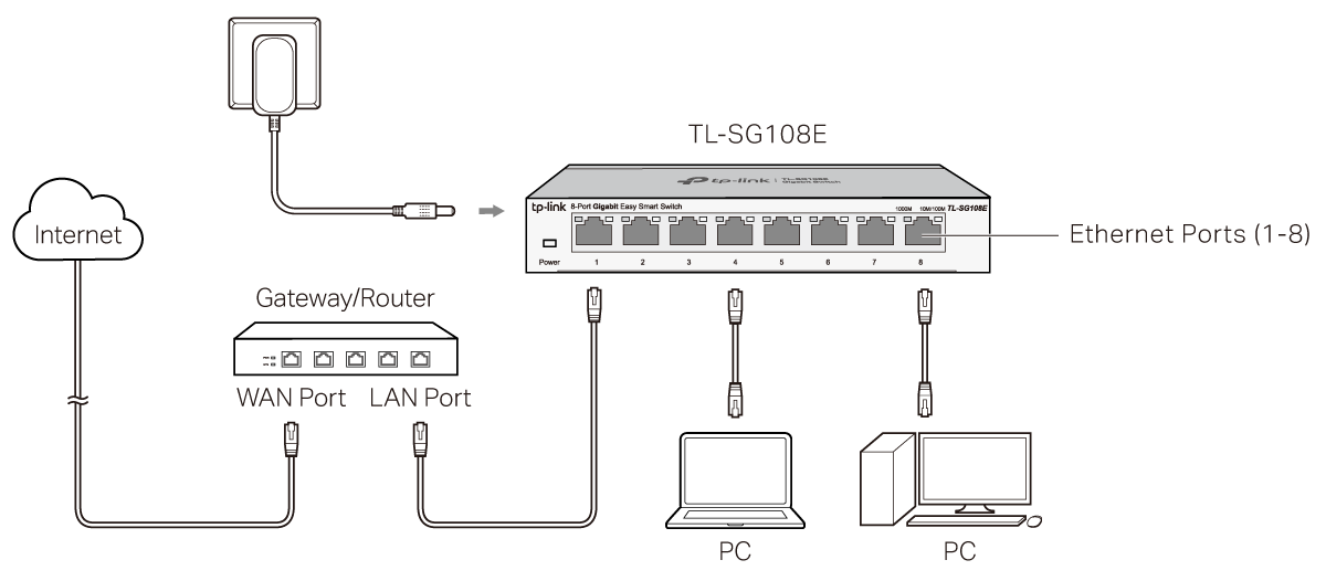
Connection
Configuration
The switch is plug and play. To configure the switch, you can use the Web-based GUI or the configuration utility. The utility is only supported on Windows now.
Using the Web-based GUI
1. Find out the IP address of the switch.
· By default, the switch receives an IP addess from a DHCP server (typically a router with DHCP function enabled) in your network. You can find out this IP address on the DHCP server.
· If the switch cannot receive an IP address from a DHCP server, it uses the static IP address of 192.168.0.1, with a subnet mask of 255.255.255.0.
2. Configure IP address on your PC to make sure the switch and PC are in the same subnet.
· If the switch uses an IP address assigned by a DHCP server, set your PC to obtain an IP address automatically from the DHCP server.
· If the switch uses 192.168.0.1 as the IP address, configure your PC’s IP address as 192.168.0.x (”x” ranges from 2 to 254), and subnet mask as 255.255.255.0.
3. Launch a web browser on your PC, enter the IP address of the switch in the address bar and press Enter. Before proceeding with further configuration, you need to set up username and password by following the prompts on the page (if prompted to log in before setting username and password, use admin for both the username and password).
Now you can configure the switch using the Web-based GUI. For further information, refer to the User Guide. Go to https://www.tp-link.com/support, search the model number of your switch, and you can find this guide on the product Support web page.
Note:
1. For certain devices, you may need to change the password the first time you log in, which will better protect your network and devices.
2. If the switch gets a new IP address from the DHCP server, your connection to the switch will be lost. Enter the new IP address in your browser to access the switch again.
Using the Configuration Utility
1. Go to https://www.tp-link.com/support and search the model number of your switch. Download the Easy Smart Configuration Utility from the product Support web page on your PC.
2. Decompress the downloaded file, run the installation wizard and follow the prompts to install the Easy Smart Configuration Utility.
3. Double click the utility icon on the desktop, and the utility Home page will display a list of TP-Link switches on the local network.
4. Click the gear icon to find out IP parameters of the switch.
· If the switch uses an IP address assigned by a DHCP server, set your PC to obtain an IP address automatically from the DHCP server.
· If the switch uses 192.168.0.1 as the IP address, configure your PC’s IP address as 192.168.0.x (”x” ranges from 2 to 254), and subnet mask as 255.255.255.0.
5. Double click the switch that you want to configure. Before proceeding with further configuration, you need to set up username and password by following the prompts on the page (if prompted to log in before setting username and password, use admin for both the username and password).
Now you can configure the switch using the configuration utility. For further information, refer to the Easy Smart Configuration Utility User Guide. Go to https://www.tp-link.com/support, search the model number of your switch, and you can find this guide on the product Support web page.
LED Explanation
| LED | Description |
|---|---|
| Power |
On: Power on Off: Power off |
| Link/Act |
1000 Mbps (Green) 10/100 Mbps (Yellow) |
Specifications
| General Specifications | |
| Standard | IEEE802.3i, IEEE802.3u, IEEE802.3ab, IEEE802.3x, IEEE802.1p, IEEE802.1q |
| Protocol | CSMA/CD |
| Interface | 5/8/16 10/100/1000 Mbps Auto-Negotiation RJ45 Ports |
| Data Transfer Rate | Ethernet: 10 Mbps (Half Duplex), 20 Mbps (Full Duplex) Fast Ethernet: 100 Mbps (Half Duplex), 200 Mbps (Full Duplex) Gigabit Ethernet: 2000 Mbps (Full Duplex) |
| Network Media (Cable) | 10Base-T: UTP category 3, 4, 5 cable (maximum 100 m) EIA/TIA-568 100 Ω STP (maximum 100 m) 100Base-TX: UTP category 5, 5e cable (maximum 100 m) EIA/TIA-568 100 Ω STP (maximum 100 m) 1000Base-T: UTP category 5e cable (maximum 100 m) EIA/TIA-568 100 Ω STP (maximum 100 m) |
| LED indicators | Power, 10/100 Mbps LED, 1000 Mbps LED |
| Transfer Method | Store-and-Forward |
| MAC Address Learning | Automatically learning, automatically aging |
| Frame Forward Rate | 10Base-T: 14881 pps/Port 100Base-TX: 148810 pps/Port 1000Base-T: 1488095 pps/Port |
| Wall Mountable | Yes |
| Distance Between Mounting Holes | TL-SG105E: 52 mm TL-SG108E: 110 mm TL-SG116E: 204.8 mm |
| Environmental and Physical Specifications | |
| Operating Temperature | 0˚C to 40˚C (32˚F to 104˚F) |
| Storage Temperature | -40˚C to 70˚C (-40˚F to 158˚F) |
| Operating Humidity | 10% to 90% RH non-condensing |
| Storage Humidity | 5% to 90% RH non-condensing |
Frequently Asked Questions (FAQ)
Q1. Why is the Power LED not lit?
The Power LED should be lit when the power system is working normally. If the Power LED is not lit, please try the following:
A1: Make sure the power adapter is connected to the switch with power source properly.
A2: Make sure the voltage of the power supply meets the requirements of the input voltage of the switch.
A3: Make sure the power source is ON.
A4: (For TL-SG105E and TL-SG108E) On the LED On/Off configuration page, check whether the LED status is on. By default, the LED status is on.
Q2. Why is the Link/Act LED not lit while a device is connected to the corresponding port?
Please try the following:
A1: Make sure that the cable connectors are firmly plugged into the switch and the device.
A2: Make sure the connected device is turned on and works normally.
A3: The cable must be less than 100 meters long (328 feet).
A4: (For TL-SG105E and TL-SG108E) On the LED On/Off configuration page, check whether the LED status is on. By default, the LED status is on.
Regulatory Compliance
FCC compliance information statement

Product Name: 5-Port Gigabit Easy Smart Switch
Model Number: TL-SG105E
Product Name: 8-Port Gigabit Easy Smart Switch
Model Number: TL-SG108PE
| Component Name | Model |
|---|---|
| Power Adapter | T050060-2B1 |
Responsible party:
TP-Link Systems Inc.
Address: 10 Mauchly, Irvine, CA 92618
Website: https://www.tp-link.com/us/
Tel: +1 626 333 0234
Fax: +1 909 527 6804
E-mail: sales.usa@tp-link.com
This equipment has been tested and found to comply with the limits for a Class B digital device, pursuant to part 15 of the FCC Rules. These limits are designed to provide reasonable protection against harmful interference in a residential installation. This equipment generates, uses and can radiate radio frequency energy and, if not installed and used in accordance with the instructions, may cause harmful interference to radio communications. However, there is no guarantee that interference will not occur in a particular installation. If this equipment does cause harmful interference to radio or television reception, which can be determined by turning the equipment off and on, the user is encouraged to try to correct the interference by one or more of the following measures:
• Reorient or relocate the receiving antenna.
• Increase the separation between the equipment and receiver.
• Connect the equipment into an outlet on a circuit different from that to which the receiver is connected.
• Consult the dealer or an experienced radio/ TV technician for help.
This device complies with part 15 of the FCC Rules. Operation is subject to the following two conditions:
1) This device may not cause harmful interference.
2) This device must accept any interference received, including interference that may cause undesired operation.
Any changes or modifications not expressly approved by the party responsible for compliance could void the user’s authority to operate the equipment.
Product Name: 16-Port Gigabit Easy Smart Switch
Model Number: TL-SG116E
| Component Name | Model |
|---|---|
| Power Adapter | T120100-2B1 |
Responsible party:
TP-Link Systems Inc.
Address: 10 Mauchly, Irvine, CA 92618
Website: https://www.tp-link.com/us/
Tel: +1 626 333 0234
Fax: +1 909 527 6804
E-mail: sales.usa@tp-link.com
This equipment has been tested and found to comply with the limits for a Class A digital device, pursuant to part 15 of the FCC Rules. These limits are designed to provide reasonable protection against harmful interference when the equipment is operated in a commercial environment. This equipment generates, uses, and can radiate radio frequency energy and, if not installed and used in accordance with the instruction manual, may cause harmful interference to radio communications. Operation of this equipment in a residential area is likely to cause harmful interference in which case the user will be required to correct the interference at his own expense:
This device complies with part 15 of the FCC Rules. Operation is subject to the following two conditions:
1) This device may not cause harmful interference.
2) This device must accept any interference received, including interference that may cause undesired operation.
Any changes or modifications not expressly approved by the party responsible for compliance could void the user’s authority to operate the equipment.
Product Name: Power Adapter
Model Number: T050060-2B1
Responsible party:
TP-Link Systems Inc.
Address: 10 Mauchly, Irvine, CA 92618
Website: https://www.tp-link.com/us/
Tel: +1 626 333 0234
Fax: +1 909 527 6804
E-mail: sales.usa@tp-link.com
This equipment has been tested and found to comply with the limits for a Class B digital device, pursuant to part 15 of the FCC Rules. These limits are designed to provide reasonable protection against harmful interference in a residential installation. This equipment generates, uses and can radiate radio frequency energy and, if not installed and used in accordance with the instructions, may cause harmful interference to radio communications. However, there is no guarantee that interference will not occur in a particular installation. If this equipment does cause harmful interference to radio or television reception, which can be determined by turning the equipment off and on, the user is encouraged to try to correct the interference by one or more of the following measures:
• Reorient or relocate the receiving antenna.
• Increase the separation between the equipment and receiver.
• Connect the equipment into an outlet on a circuit different from that to which the receiver is connected.
• Consult the dealer or an experienced radio/ TV technician for help.
This device complies with part 15 of the FCC Rules. Operation is subject to the following two conditions:
1) This device may not cause harmful interference.
2) This device must accept any interference received, including interference that may cause undesired operation.
Any changes or modifications not expressly approved by the party responsible for compliance could void the user’s authority to operate the equipment.
Product Name: Power Adapter
Model Number: T120100-2B1
Responsible party:
TP-Link Systems Inc.
Address: 10 Mauchly, Irvine, CA 92618
Website: https://www.tp-link.com/us/
Tel: +1 626 333 0234
Fax: +1 909 527 6804
E-mail: sales.usa@tp-link.com
This equipment has been tested and found to comply with the limits for a Class A digital device, pursuant to part 15 of the FCC Rules. These limits are designed to provide reasonable protection against harmful interference when the equipment is operated in a commercial environment. This equipment generates, uses, and can radiate radio frequency energy and, if not installed and used in accordance with the instruction manual, may cause harmful interference to radio communications. Operation of this equipment in a residential area is likely to cause harmful interference in which case the user will be required to correct the interference at his own expense:
This device complies with part 15 of the FCC Rules. Operation is subject to the following two conditions:
1) This device may not cause harmful interference.
2) This device must accept any interference received, including interference that may cause undesired operation.
Any changes or modifications not expressly approved by the party responsible for compliance could void the user’s authority to operate the equipment.
We, TP-Link Systems Inc., has determined that the equipment shown as above has been shown to comply with the applicable technical standards, FCC part 15. There is no unauthorized change is made in the equipment and the equipment is properly maintained and operated.
Issue Date: 2025-11-18
Industry Canada Statement
TL-SG105E/TL-SG108E: CAN ICES-003 (B)/NMB-003(B)
TL-SG116E: CAN ICES-003 (A)/NMB-003(A)
CE Mark Warning

TL-SG116E: This is a class A product. In a domestic environment, this product may cause radio interference, in which case the user may be required to take adequate measures.
For TL-SG105E/TL-SG108E:
TP-Link hereby declares that the switch is in compliance with the essential requirements and other relevant provisions of directives 2014/30/EU, 2014/35/EU, 2009/125/EC, 2011/65/EU and (EU)2015/863.
The original EU declaration of conformity may be found at https://www.tp-link.com/en/support/ce/
For TL-SG116E:
TP-Link hereby declares that the switch is in compliance with the essential requirements and other relevant provisions of directives 2014/30/EU, 2014/35/EU, 2011/65/EU and (EU)2015/863.
The original EU declaration of conformity may be
UKCA Mark

TP-Link hereby declares that the switch is in compliance with the essential requirements and other relevant provisions of the Electromagnetic Compatibility Regulations 2016 and Electrical Equipment (Safety) Regulations 2016.
The original UK declaration of conformity may be found at https://www.tp-link.com/support/ukca/
Safety Information
· Keep the device away from water, fire, humidity or hot environments.
· Do not attempt to disassemble, repair, or modify the device. If you need service, please contact us.
· Place the device with its bottom surface downward.
· Do not use damaged charger or USB cable to charge the device.
· Do not use any other chargers than those recommended.
· Adapter shall be installed near the equipment and shall be easily accessible.
· Use only power supplies which are provided by manufacturer and in the origin
· Use only power supplies listed in the user instructions. Refer to the User Manual on the product support page.
For the EU countries, use only the power adapters listed below:
| Model | Power Adapter | Manufacturer |
|---|---|---|
| TL-SG105E | T050060-2C1 | TP-Link |
| TL-SG108E | T050060-2C1 | TP-Link |
| TL-SG116E | T120100-2C1 | TP-Link |
· 運作溫度: 0°C~40°C。
TL-SG116E:
この装置は、クラスA情報技術装置です。この装置を家庭環境で使用すると電波妨害を引き起こすことがあります。この場合には使用者が適切な対策を講ずるよう要求されることがあります。 VCCI-A
BSMI Notice
安全諮詢及注意事項
- 請使用原裝電源供應器或只能按照本產品注明的電源類型使用本產品。
- 清潔本產品之前請先拔掉電源線。請勿使用液體、噴霧清潔劑或濕布進行清潔。
- 注意防潮,請勿將水或其他液體潑灑到本產品上。
- 插槽與開口供通風使用,以確保本產品的操作可靠並防止過熱,請勿堵塞或覆蓋開口。
- 請勿將本產品置放於靠近熱源的地方。除非有正常的通風,否則不可放在密閉位置中。
- 不要私自拆開機殼或自行維修,如產品有故障請與原廠或代理商聯繫。
警告:為避免電磁干擾,本產品不應安裝或使用於住宅環境。
限用物質含有情況標示聲明書
|
設備名稱 :Switch Equipment name |
型號(型式) :TL-SG105E/TL-SG108E/TL-SG116E Type designation (Type) |
|||||
|---|---|---|---|---|---|---|
| 單元 Unit |
限用物質及其化學符號 Restricted substances and its chemical symbols |
|||||
| 鉛 Lead (Pb) |
汞 Mercury (Hg) |
鎘 Cadmium (Cd) |
六價鉻 Hexavalent chromium (Cr+6) |
多溴聯苯 Polybrominated biphenyls (PBB) |
多溴二苯醚 Polybrominated diphenyl ethers (PBDE) |
|
| PCB | ○ | ○ | ○ | ○ | ○ | ○ |
| 外殼 | ○ | ○ | ○ | ○ | ○ | ○ |
| 電源供應器 | − | ○ | ○ | ○ | ○ | ○ |
| 其他與配件 | − | ○ | ○ | ○ | ○ | ○ |
| 備考1.〝超出0.1 wt %〞及〝超出0.01 wt %〞係指限用物質之百分比含量超出百分比含量基準值 Note 1:“Exceeding 0.1 wt %” and “exceeding 0.01 wt %” indicate that the percentage content of the restricted substance exceeds the reference percentage value of presence condition. 備考2.〝○〞係指該項限用物質之百分比含量未超出百分比含量基準值。 Note 2:“○” indicates that the percentage content of the restricted substance does not exceed the percentage of reference value of presence. 備考3.〝-〞係指該項限用物質為排除項目。 Note 3:The “−” indicates that the restricted substance corresponds to the exemption. |
||||||

Продукт сертифіковано згідно с правилами системи УкрСЕПРО на відповідність вимогам нормативних документів та вимогам, що передбачені чинними законодавчими актами України.

Explanation of the symbols on the product label
Note: The product label can be found at the bottom of the product and its I.T.E. power supply. Symbols may vary from products.
注意:產品標籤可以在產品底部和其I.T.E.電源供應器上找到。產品標籤可在產品底部找到。符號可能因產品而異。
| Symbol 符號解釋 |
Explanation 解釋 |
|---|---|
 |
Class II equipment Class II 設備 |
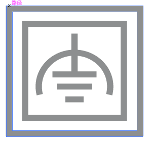 |
Class II equipment with functional earthing 具有功能接地的Class II 設備 |
 |
Alternating current 交流電 |
 |
DC voltage 直流電壓 |
 |
Polarity of output terminals 輸出端子極性 |
 |
Indoor use only 僅限室內使用 |
 |
Dangerous voltage 危險電壓 |
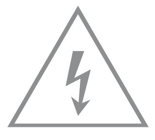 |
Caution, risk of electric shock 注意,有觸電危險 |
 |
Energy efficiency Marking 能源效率標示 |
 |
Protective earth 保護地線 |
 |
Earth 地線 |
 |
Frame or chassis 機架接地 |
 |
Functional earthing 功能地線 |
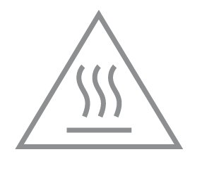 |
Caution, hot surface 警告,表面高溫 |
 |
Caution 警告 |
 |
Operator’s manual 操作手冊 |
 |
Stand-by 待機 |
 |
“ON”/”OFF” (push-push) 「開」/「關」 ( 按壓式) |
 |
Fuse 保險絲 |
 |
Fuse is used in neutral N 保險絲用於中性線N |
 |
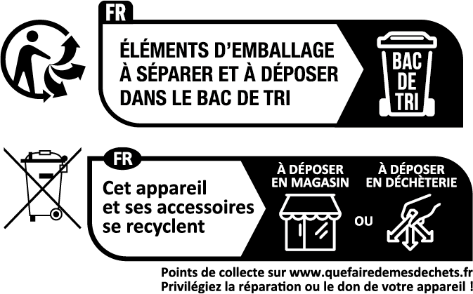
RECYCLING This product bears the selective sorting symbol for Waste electrical and electronic equipment (WEEE). This means that this product must be handled pursuant to European directive 2012/19/EU in order to be recycled or dismantled to minimize its impact on the environment. User has the choice to give his product to a competent recycling organization or to the retailer when he buys a new electrical or electronic equipment. 回收利用 本產品標示有「廢棄電氣電子設備(WEEE)」的分類回收標誌。這表示本產品必須依據歐盟指令 2012/19/EU 進行妥善回收或拆 解,以減少對環境的影響。 使用者可選擇將本產品交給合格的回收機構,或在購買新電器或電子設備時,交回給零售商進行回收處理。 |
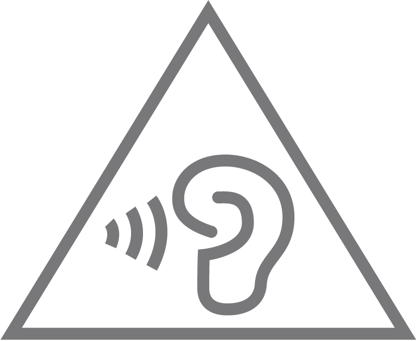 |
Caution, avoid listening at high volume levels for long periods 注意,避免長時間以高音量收聽 |
 |
Disconnection, all power plugs 斷開所有電源插頭 |
Wall Mounting Requirements
TL-SG105E/TL-SG108E:
To mount the device on a wall, use 2 screws which complies with ANSI B1.1 4#, (5#), 6# standard and are more than 7.5 mm in length. When the screws are fixed on the wall, the distance between the screw head and the wall should be more than 1.5 mm.
TL-SG116E:
To mount the device on a wall, use 2 screws which complies with ANSI B1.1 4#, (5#), 6# standard and are more than 8.5 mm in length. When the screws are fixed on the wall, the distance between the screw head and the wall should be more than 1.5 mm.
牆面安裝要求
TL-SG105E/TL-SG108E:
將設備安裝到牆上,需使用 2 顆符合 ANSI B1.1 4#、(5#)、6#標準、長度大於 7.5mm 的螺絲,螺絲固定在牆上時,螺絲頭與牆面的距離應大於 1.5mm。
TL-SG116E:
將設備安裝到牆上,需使用 2 顆符合 ANSI B1.1 4#、(5#)、6#標準、長度大於 8.5mm 的螺絲,螺絲固定在牆上時,螺絲頭與牆面的距離應大於 1.5mm。