How to install HS200 to your electrical line
Before we start, please note that your socket is applicable:
How can I install HS200 if my powerline socket only contains 3 lines?
For HS200
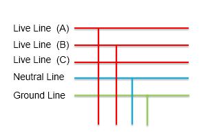
Let’s know about the electrical line at first. As we know, power transmission usually take the form of three phase four wire.
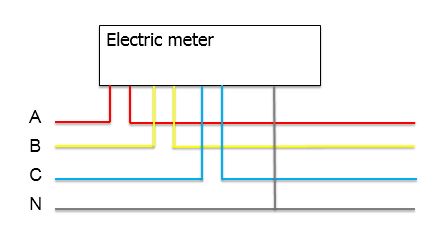
Live/Load line: There will generate voltage (100 ~ 240V) between A/B/C line and N line, we call A, B and C line live/load line.
Neutral line: Due to the three-phase equilibrium (A, B and C line are connected together at N line), there is no current flows through N line, we call it neutral line.
Ground line: Because the earth is a good conductor, we use a line to connect the shell of device/electrical appliance and the earth to avoid electrical shock hazards, we call the line ground line.
In general, the electrical line will supply two live lines, one neutral line and one ground line to you to install socket or switch.
Now let’s install the TP-Link smart switch to your electrical line.
Note: If you’re not familiar with basic electrical work, please don’t install switch by yourself, and call a professional electrician to help you.
Step 1:Please confirm whether your electrical line meet the following electrical requirements below:
- A neutral line. (If there is no neutral line in the wall box, STOP installing the switch and consult with a professional electrician).
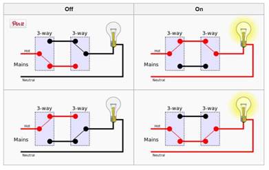
- A single pole switch (TP-Link smart switch is not 3-way switch).
3. Due to TP-Link smart switch need to be configured by Wi-Fi, it can only be installed in non-metal faceplates and dry indoor locations.
If you have met the electrical requirements, proceed with the electrical installation instructions below.
Step 2: Turn off power at the circuit breaker that controls the light switch. Use voltage tester to confirm no voltage is present.
Step 3:Remove existing faceplate and light switch, then identify Live/Load, Neutral and Ground lines.
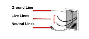
Step 4:Connect the Smart Switch wiring with the provided wire connectors as follows.
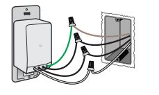
Connect each of the two black wires from the switch to the available Live lines via the wire nut, and wrap electrical tape around the wire nuts to make sure the copper conductor
is fully concealed. Green wire on switch (Ground line) to Ground line, White wire on switch (Neutral line) to Neutral line.
Note: The following wiring scenarios may be dangerous or illegal.
- If the Neutral line is not available. Don’t install!
- Never connect the Neutral line to any Switch lines.
Step 5:Mount the Smart Switch onto the wall box using the two screws provided, and snap on the included wall plate or attach your existing one.
Note: The included wall plate is intended for single gang box installation only.
Step 6:Restore power to the Smart Switch at the circuit breaker, and enjoy it.
Get to know more details of each function and configuration please go to Download Center to download the manual of your product.
Is this faq useful?
Your feedback helps improve this site.
