
Table of Contents
Archer NX500-Outdoor_V1_Product and Installation Guide
About This Guide
This guide provides a brief introduction to 5G Outdoor/Indoor Router and regulatory information.
Note: Features available in this outdoor router may vary by model and software version. Router availability may also vary by region or ISP. All images, steps, and descriptions in this guide are only examples and may not reflect your actual router experience.
Conventions
In this guide the following conventions are used:
|
Convention |
Description |
|
Underline |
Underlined words or phrases are hyperlinks. You can click to redirect to a website or a specific section. |
|
Bold |
Contents to be emphasized and texts on the web page are in bold, including the menus, items, buttons and so on. |
|
> |
The menu structures to show the path to load the corresponding page. For example, Advanced > System Tools > Firmware Upgrade means the Firmware Upgrade page is under the System Tools menu that is located in the Advanced tab. |
|
Note: |
Ignoring this type of note might result in a malfunction or damage to the device. |
|
Tip: |
Indicates important information that helps you make better use of your device. |
More Info
The latest software, management app and utility can be found at Download Center at https://www.tp-link.com/support/download/.
The Quick Installation Guide can be found where you find this guide or inside the package of the router.
Specifications can be found on the product page at https://www.tp-link.com.
TP-Link Community is provided for you to discuss our products and share knowledge at https://community.tp-link.com.
Our Technical Support contact information can be found at the Contact Technical Support page at https://www.tp-link.com/support/.
Disclaimer
*Maximum wireless signal rates are the physical rates derived from IEEE Standard 802.11 specifications. Actual wireless data throughput and wireless coverage are not guaranteed and will vary as a result of 1) environmental factors, including building materials, physical objects, and obstacles, 2) network conditions, including local interference, volume and density of traffic, product location, network complexity, and network overhead, and 3) client limitations, including rated performance, location, connection, quality, and client condition.
*Use of Wi-Fi 6 (802.11ax), and features including OFDMA, MU-MIMO, 1024-QAM, and HT160 require clients to also support the corresponding features.
*Saving clients’ battery power requires clients to also support the 802.11ax Wi-Fi standard. Actual power reduction may vary as a result of network conditions, client limitations, and environmental factors.
*Use of WPA3 requires clients to also support the corresponding feature.
*This router may not support all the mandatory features as ratified in Draft 3.0 of IEEE 802.11ax specification.
*Further software upgrades for feature availability may be required.
1. Get to Know About Your Router
1.1 Product Overview
TP-Link’s Router is a combined wired/wireless network connection device with integrated WAN router, reducing hassle of configuration and saving space.
With Ethernet ports and antennas, the router provides wired and wireless access for multiple computers and mobile devices.
With various features and functions, the router is the perfect hub of your home or business network.
Moreover, it is simple and convenient to set up and use the TP-Link router due to its intuitive Tether app and powerful web interface.
1.2 Appearance
1.2.1 Top Panel
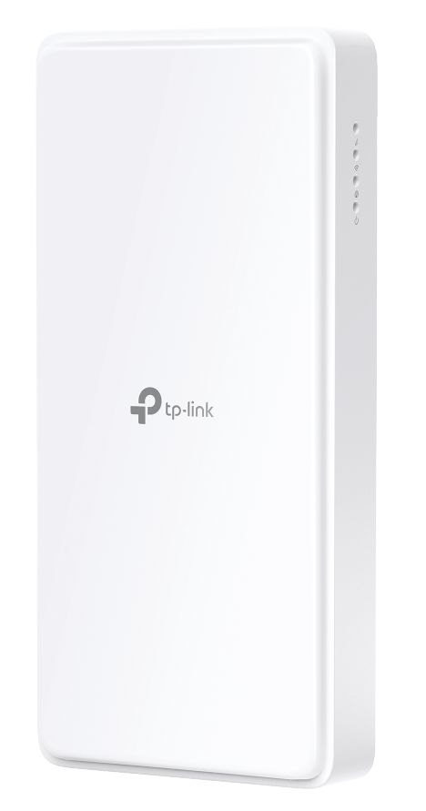
The router’s LEDs (view from top to bottom) are located on the right side. You can check the router’s working status by following the LED Explanation table.
|
Name |
Status |
Indication |
|---|---|---|
|
(Signal Strength) |
Green | The signal strength is above 75%. |
| Yellow | The signal strength is between 50% and 75%. | |
| Red |
The signal strength is below 50%. |
|
| Off | No mobile network signal. | |
|
(Wi-Fi) |
On | The Wi-Fi is enabled. |
| Off | The Wi-Fi is disabled. | |
|
(Network Type) |
Green | The device is on a 5G network. |
| Yellow | The device is on a 4G network. | |
| Red | The device is on a 3G network. | |
| Off | The device is not registered on the network. | |
|
(Power) |
Green |
The device is powered on and working properly. |
|
Flashing |
The device is initializing, RESET or upgrading. | |
| Off | The device is powered off. |


1.2.2 The Back and Bottom Panel
1.0_B_20260225065537m.png)
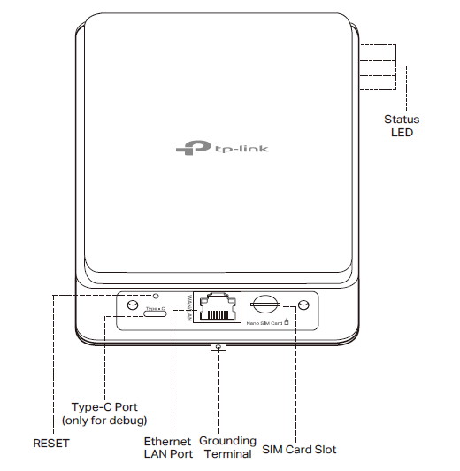
The following parts (view from top to bottom) are located on the back panel.
|
Item |
Description |
|---|---|
| Reset | Press and hold this button for at least 5 seconds until all LEDs blink to reset the router to its factory default settings. |
| Type-C Port | Only for debugging. |
| Ethernet LAN Port | For connecting the router to a PoE adapter or a PoE switch. |
| Grounding Terminal | Provide a grounding connection to ensure the safe operation and stability of the equipment. |
| Nano SIM Card Slot | For inserting a Nano SIM card (not included in the package) to the router. |
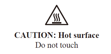
Caution: DO NOT touch the back cover when the router is working, as this may cause burns from high temperature.
2. Connect the Hardware
Videos for Your Quick Setup
To mount your router to a wall or a window, refer to the video: How to mount TP-Link 5G Outdoor router to a wall or a window
To mount your router to a pole, refer to the video: How to mount TP-Link 5G Outdoor router to a pole
To configure your router, refer to the video: How to Configure TP-Link 5G Outdoor Router
2.1 Install Lightning and ESD Protection
Before mounting the Outdoor Router, you should consider Lightning and ESD Protection to ensure safety.
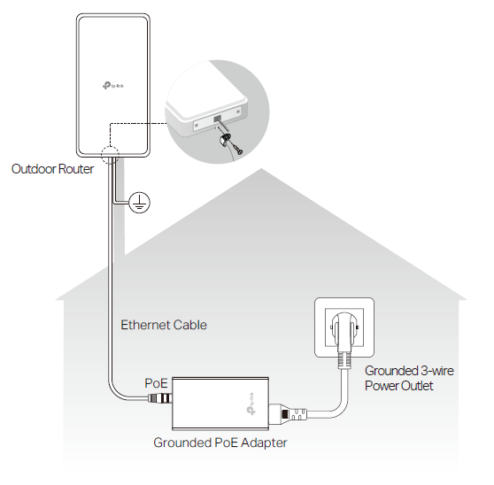
Proper grounding is extremely important for outdoor devices. To reduce the damage of potential lightning and ESD attacks, connect the grounding terminal to grounding facilities using a proper grounding wire, which should meet the local installation requirements. You need to secure the grounding wire to the grounding terminal with the screw.
*Plug the adapter into the wall outlets with earthing connection through the power cord plug.
2.2 Determine the Power Option
The outdoor router can be powered by a power adapter, a passive PoE adapter, a PSE device (such as a PoE switch) which complies with Power Source Class 2 (PS2) or Limited Power Source (LPS) of IEC 62368-1.
Option 1: Via Passive PoE Adapter
1. Connecting the PoE Adapter
Connect the Outdoor Router to a Power over Ethernet (PoE) adapter as follows:
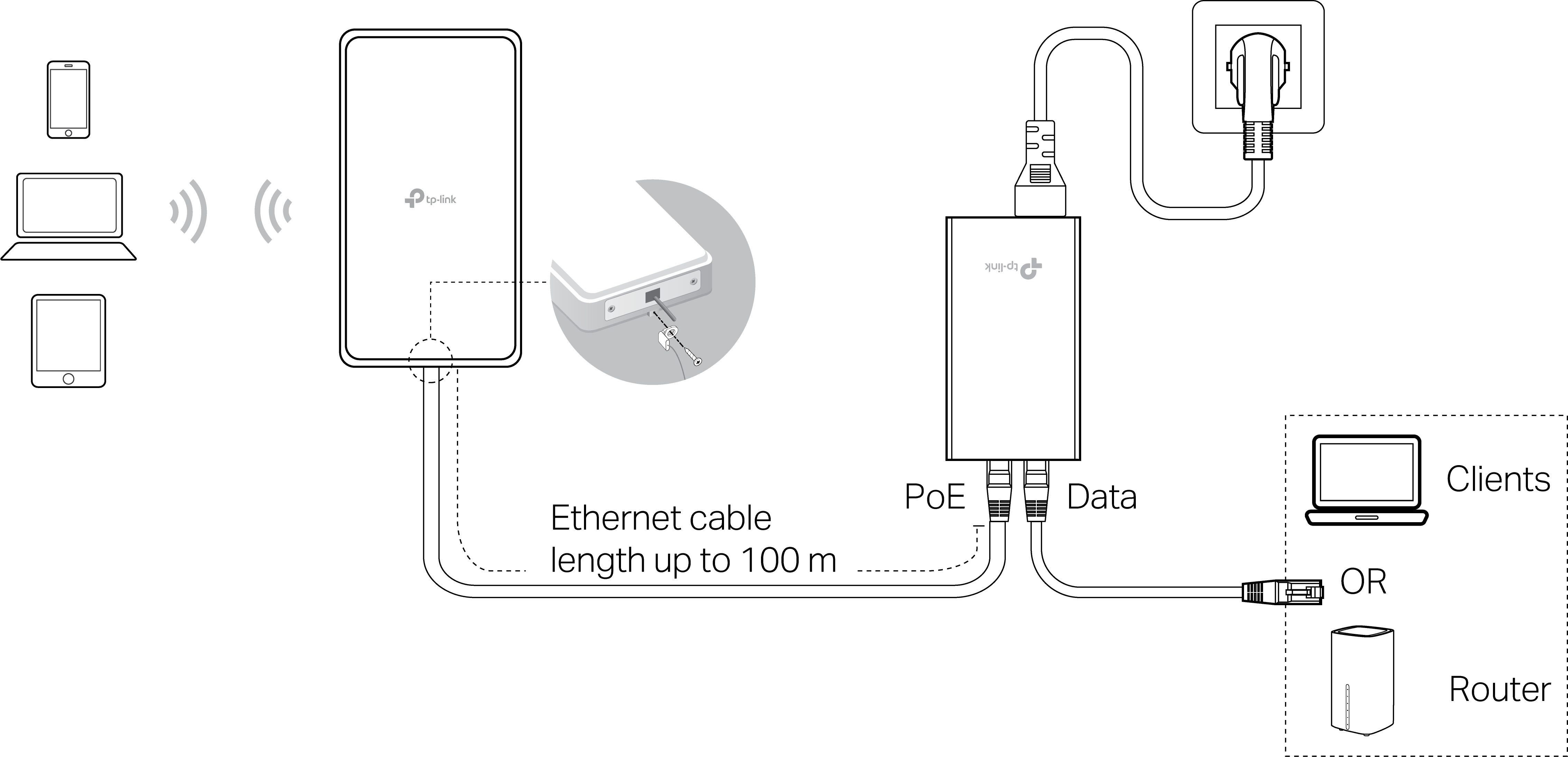
2. Mounting the PoE Adapter (Optional)
Note: To ensure the passive PoE adapter is attached most securely, it is recommended to install the adapter with the Ethernet port facing upward.
1) Remove the mounting bracket from the passive PoE Adapter.
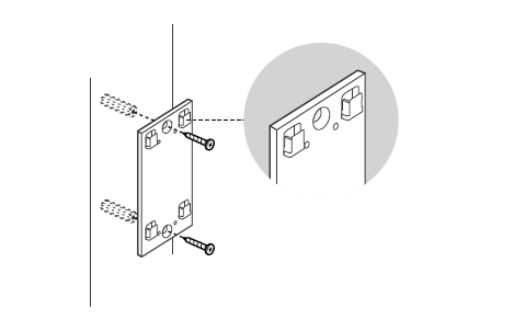
2) Drill two holes on the wall and insert the plastic wall anchors into the holes. Secure the mounting bracket to the wall. Make sure the shoulders at the corners of the mounting bracket are on the outside and pointing upward.
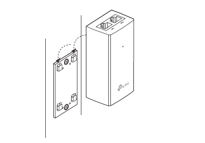
3) Attach the passive PoE adapter to the mounting bracket (for PoE Adapter) by sliding the adapter in the direction of the arrows until it locks into place.
Option 2: Via PoE Switch
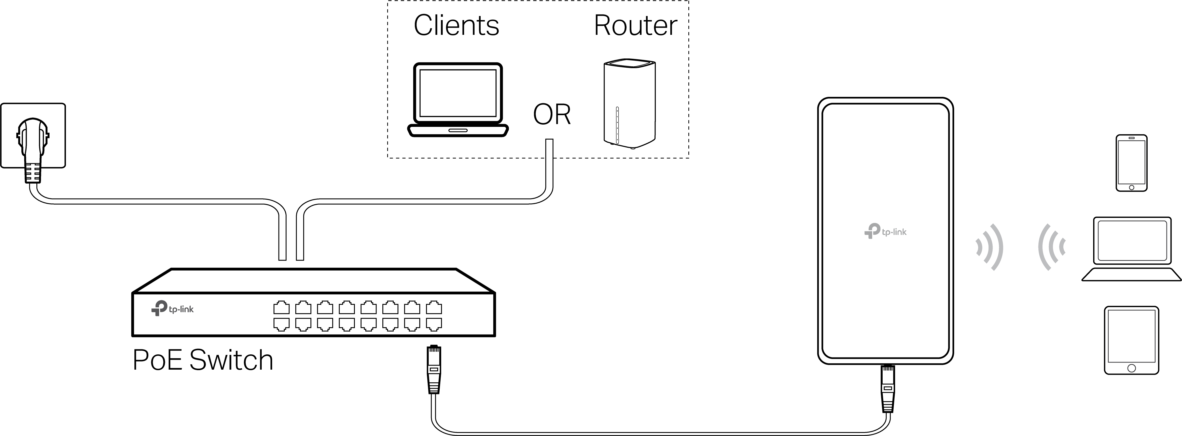
Connect an Ethernet cable from the PoE switch (compliant with 802.3af) to the router’s Ethernet port.
2.3 Waterproof the Router
The Router can be used either indoors or outdoors. Before mounting your router outdoors, waterproof it to ensure device safety and performance.
Note: The outdoor router can only be used in upright direction as shown in the image.
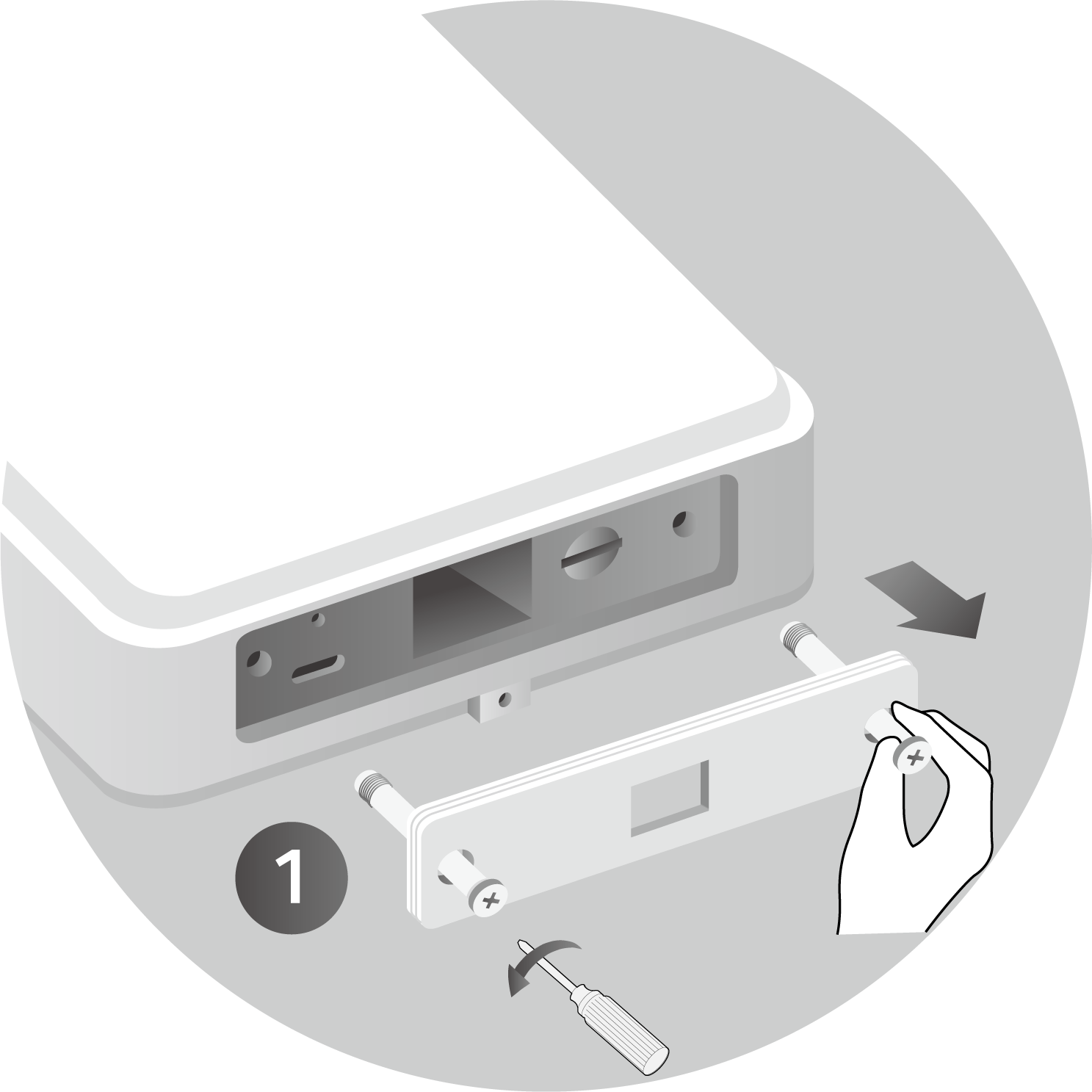
1. Loosen the screws with a Phillips screwdriver while holding them securely, then detach the Waterproof Cover Plate by pulling it outward with your hand.
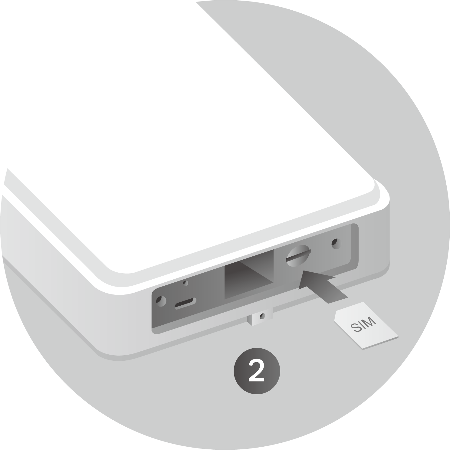
2. With the gold contacts facing down, insert the nano SIM card into the slot until you hear a click.
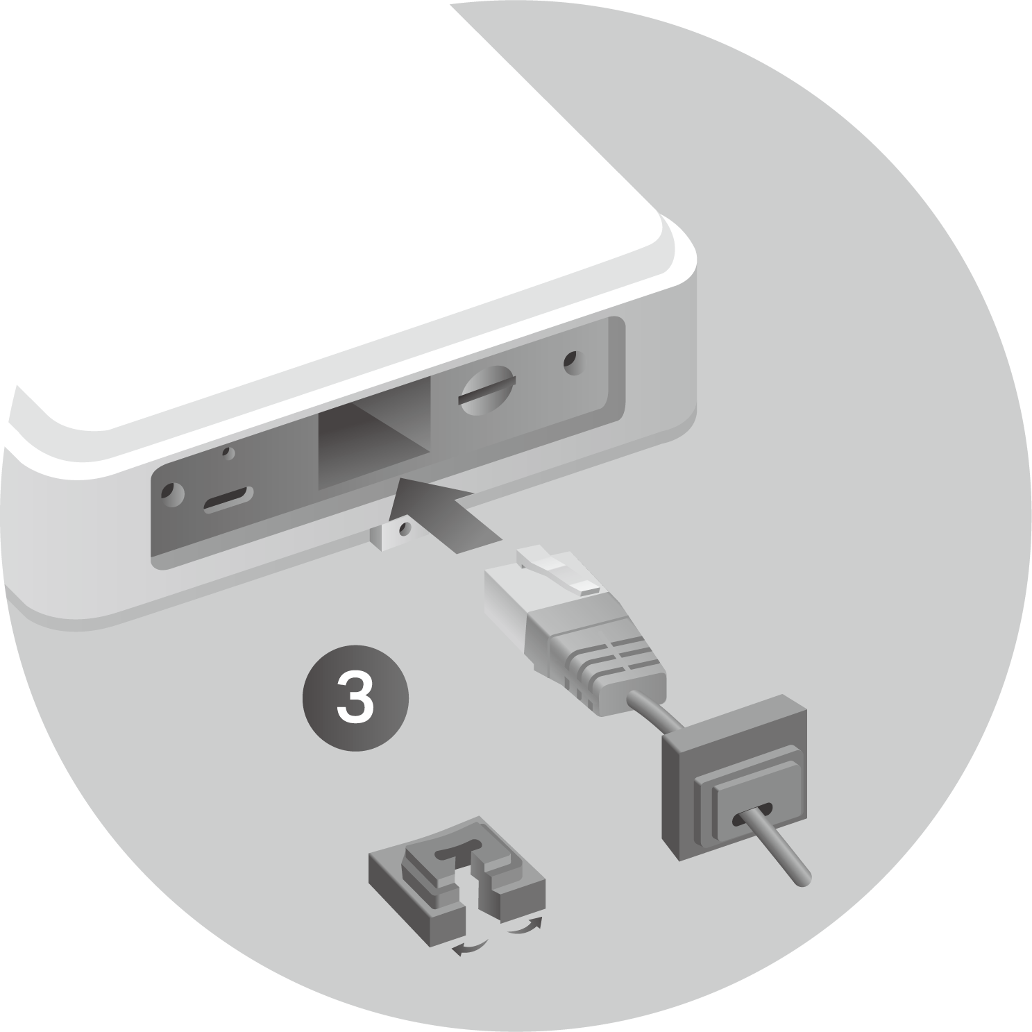
3. First fit an Ethernet cable through the Waterproof Cover Plate, then through the Rubber Stopper’s slit.
Note: The wider side of the Rubber Stopper should face the port.
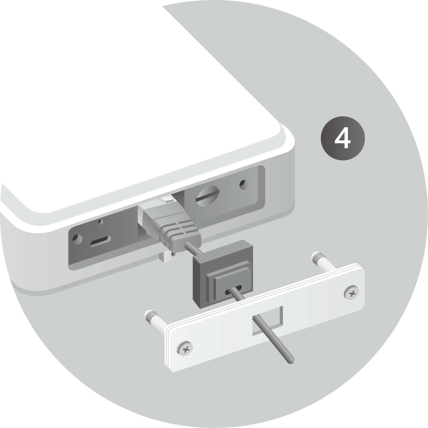
4. Connect the cable to the port and replace the Waterproof Cover Plate, leading the cable through the slot of the plate.
Note: Please align the Rubber Stopper to the Slot of the Waterproof Cover Plate.
2.4 Detect Optimal Position
Before You Start: Verify the Hardware Connection
Check the following LEDs’ status. If the Network LED is on, your Outdoor Router is connected to the internet successfully.
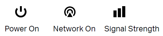
Note: If the Network LED does not turn on, please refer to Q2 of FAQ in this guide.
For better Internet connectivity, make sure the LEDs are lit in green or yellow.
Otherwise, try relocating the router to a spot where a stronger mobile network signal can be received.
Step 1. Set up your Tether App
1. Download the Tether app.

2. Open the Tether app and log in with your TP-Link ID.
Note: If you don’t have an account, create one first.
Step 2. Connect to the Outdoor Router
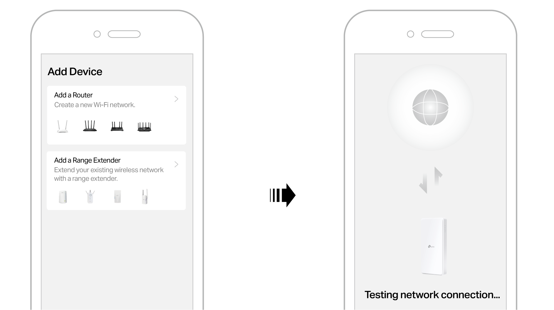
Tap the + button and select Add a Router. Follow the steps to complete the setup.
Note: Due to Tether app updates, your actual interface and pathway may differ from those depicted here.
Step 3. Detect and Adjust Installation Position
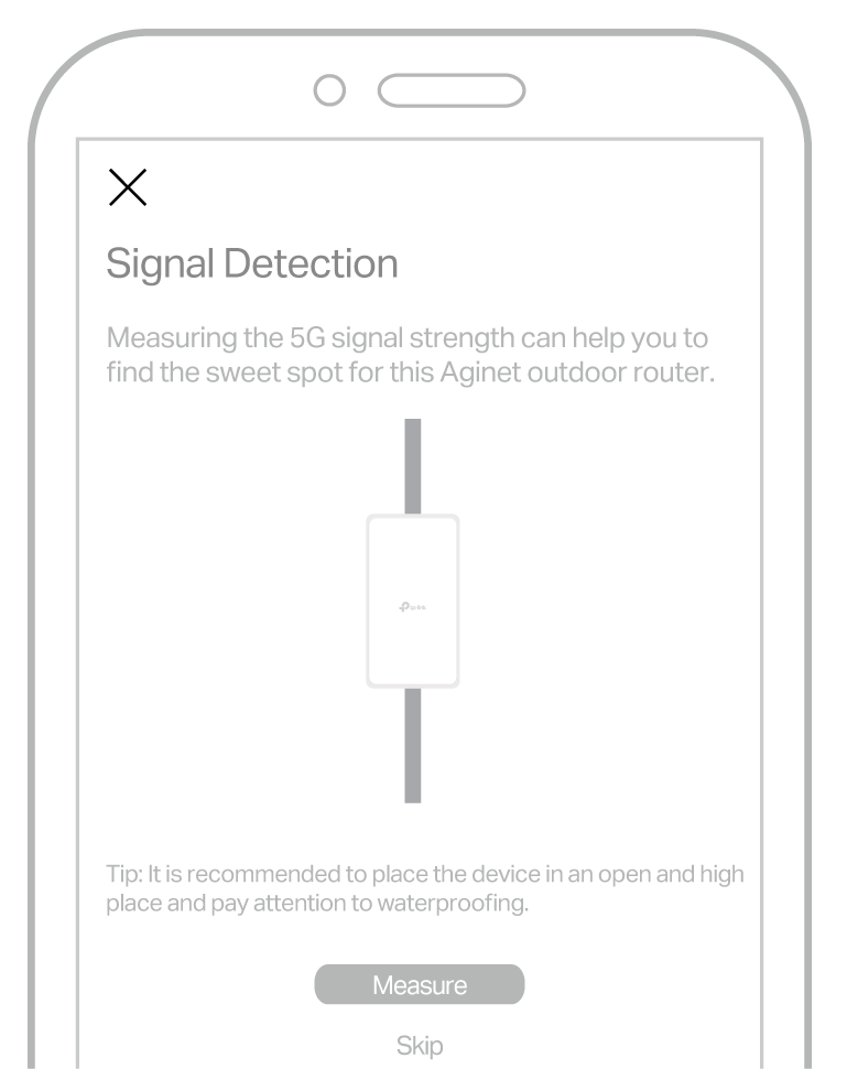
1. Place your router at a desired place on the pole/wall/window, and tap Measure to begin signal detection.
Tips:
a. To get a more accurate result, please don’t move around your router while measuring.
b. You can also tap Skip if you want to use the router’s current position.
2. The signal strength at the current position is displayed (Excellent, Good, Fair, Weak and No Signal). You can tap More Detail to view the network details.
3. Follow the on-screen instructions to continue measuring until an ideal position is detected.
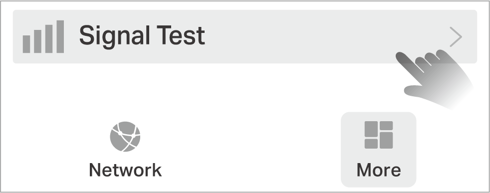
Note: Go to More > Signal Test, you can view the last 10 measure records and select the desired installation location.
4. After determining the installation position, please disconnect the PoE adapter from the device for a safe mounting.
2.5 Mount the Router
The router can be mounted to a pole, a wall or a window. Choose the appropriate mounting methods.
Note: The outdoor router can only be used in upright direction as shown in the image.
Method 1: Pole Mounting
Before mounting, please choose suitable tools for different poles.
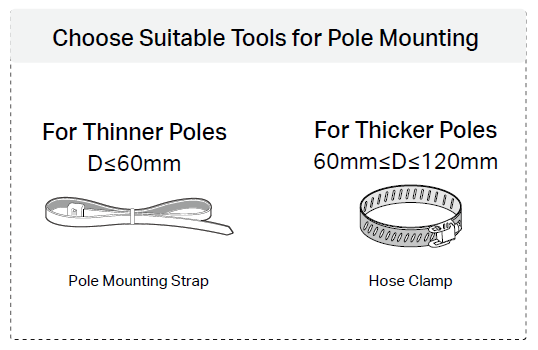
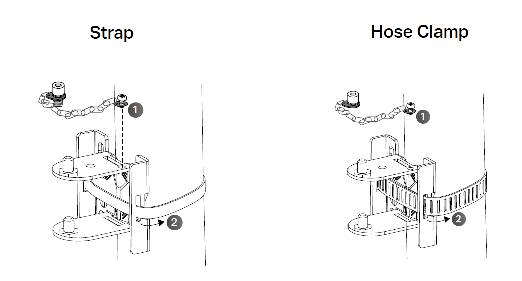
1. Install the mounting strap/chain bolt to the bracket. Lead the end of the pole mounting strap through the groove on the bracket to install the bracket against the pole.
Note: You can secure the mounting bracket vertically or horizontally as needed.
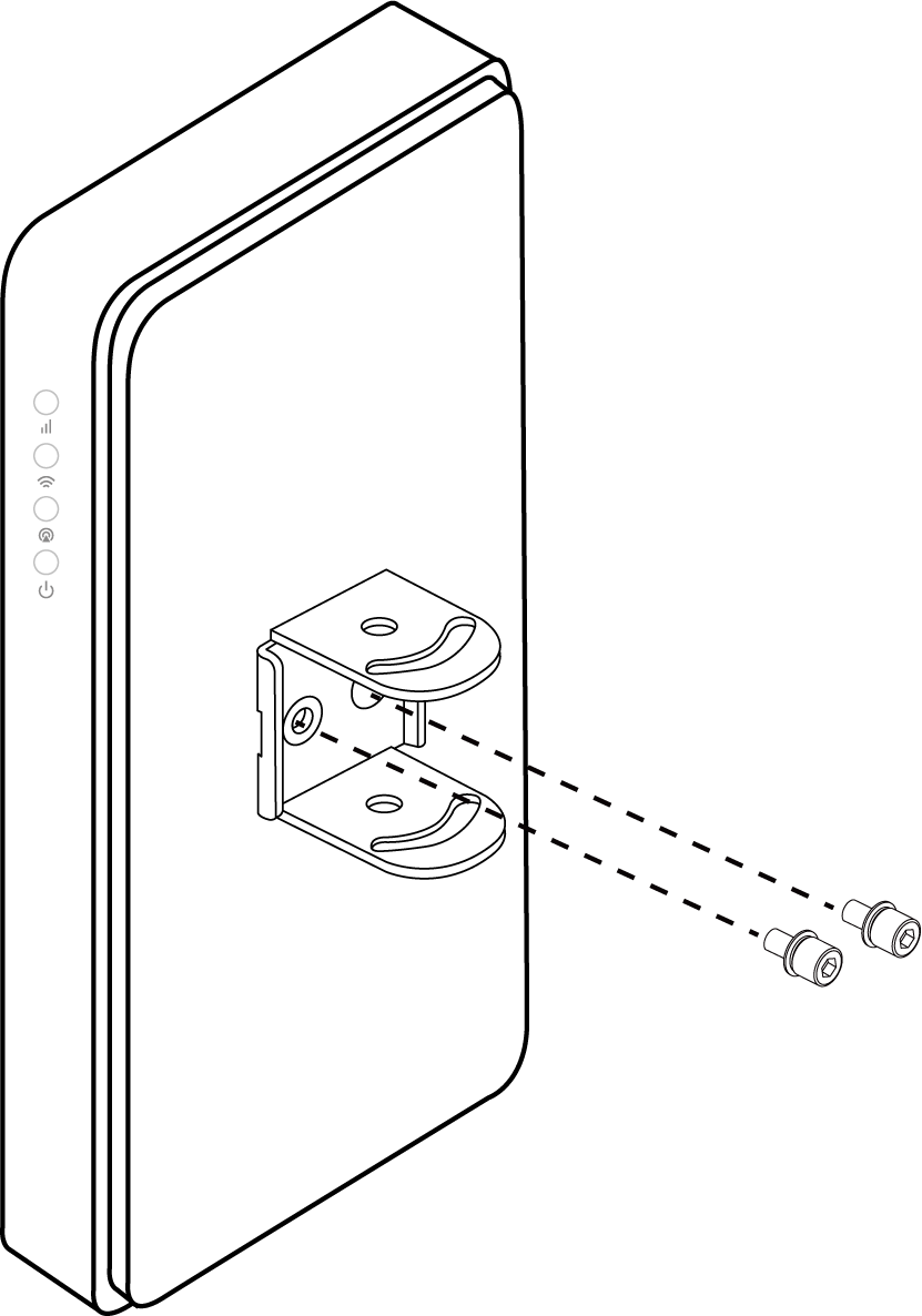
2. Use two M5 hex socket screws to install the backplane to the Outdoor Router.
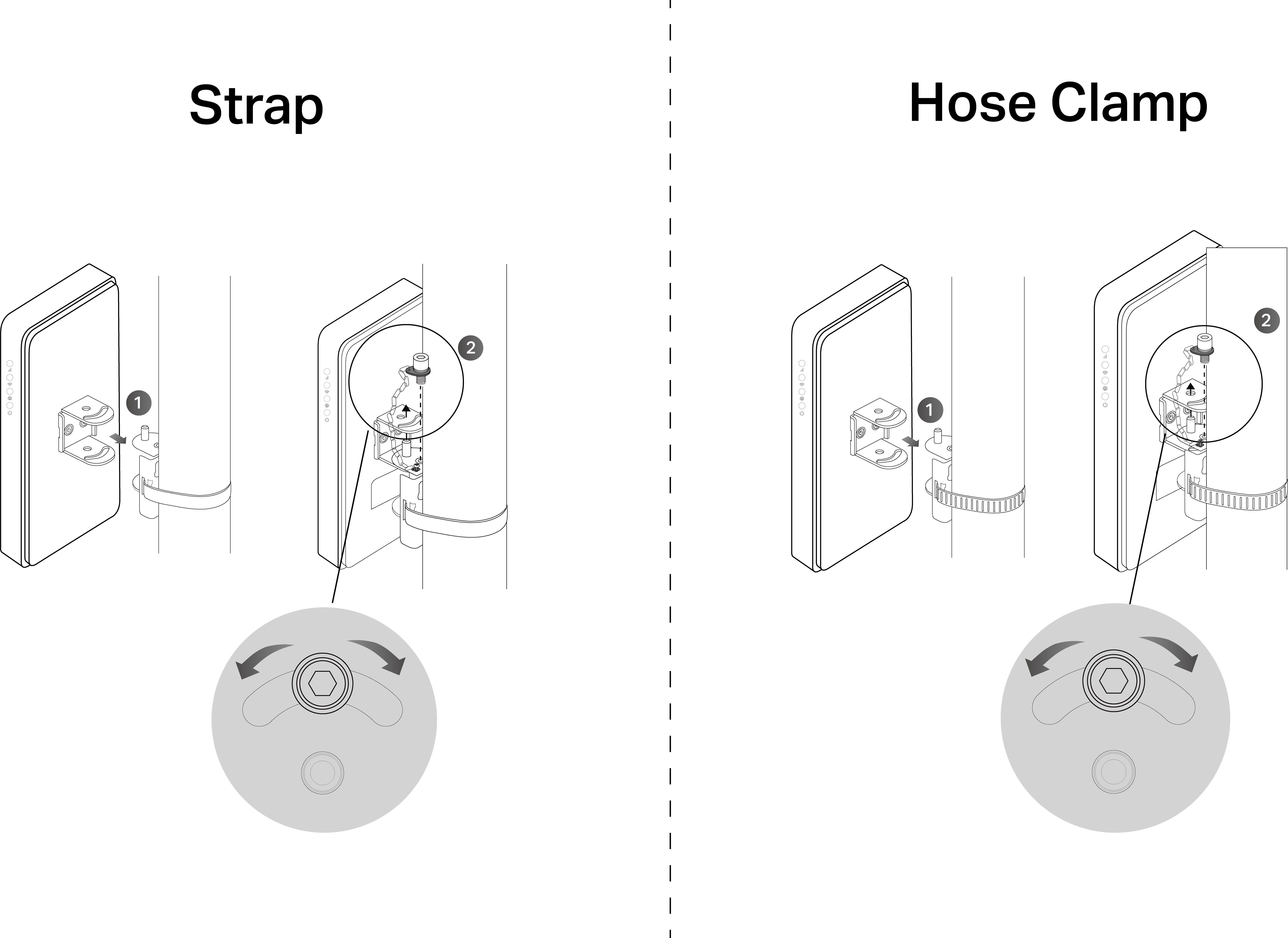
3. Align the backplane on the back of the Outdoor Router with the slot of the mounting bracket. Push and slide the Outdoor Router down until it locks into place. Use the chain bolt to secure the backplane and mounting bracket.
Note: You can adjust the installation angle horizontally as needed, with an adjustment range of 90°.
Tips for Hose Clamp:
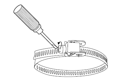
1. Release your clamp
Step1: Loosen the screw-lock to unlock the hose clamp with a screwdriver.
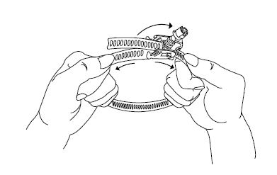
Step 2: Open the screw-lock, hold the metal straps on both sides of the screw-lock with your hands and apply force to opposite direction together. Then the lock will loosen and pop out, unlocking the hose clamp.
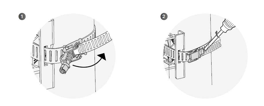
2. Secure your clamp
Lead the hose clamp through the mounting bracket and the screw-lock, and adjust it to a suitable position. Press down the screw-lock and tighten it with a screwdriver (turn right).
Method 2: Wall Mounting
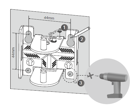
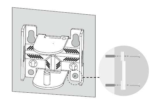
1. Install the chain bolt to the bracket. Place the mounting bracket in the right position. Mark four positions for the screw holes. Drill four 6 mm holes for the screws at the marked positions.
2. Insert the plastic wall anchors into the 6 mm holes. Align the bracket to the plastic wall anchors and drive the self-tapping screws into the anchors through the bracket.
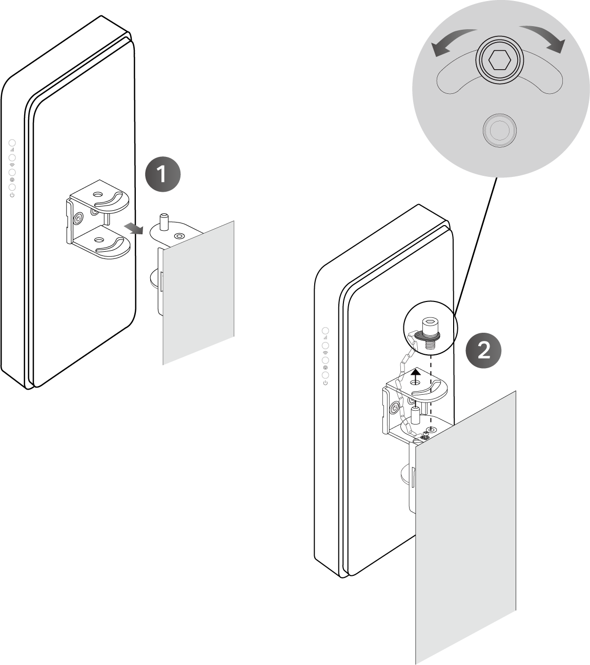
3. Use two M5 hex socket screws to install the backplane on the Outdoor Router.
4. Align the backplane on the back of the Outdoor Router with the slot of the mounting bracket. Push and slide the Outdoor Router down until it locks into place. Use the chain bolt to secure the backplane and mounting bracket.
Note: You can adjust the installation angle horizontally as needed, with an adjustment range of 90°.
Method 3: Window Mounting
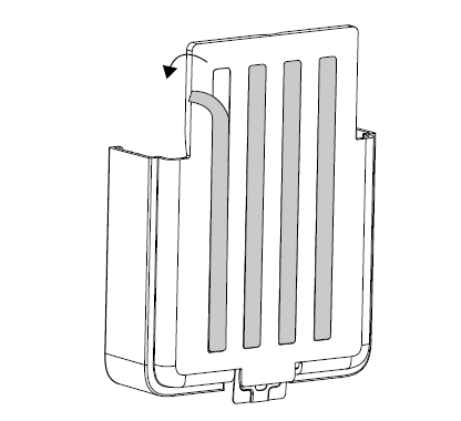
1. Tear off the double-sided tape behind the mounting bracket, and stick the bracket on the window.
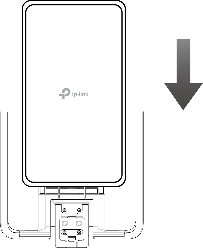
2. Align the Outdoor Router with the slot of the mounting bracket. Push and slide the Outdoor Router down until it locks into place.
3. If you want to remove the Outdoor Router from the mounting bracket, please press and hold the metal clip at the bottom of the mounting bracket. Then push and slide the Outdoor Router up until it is removed.
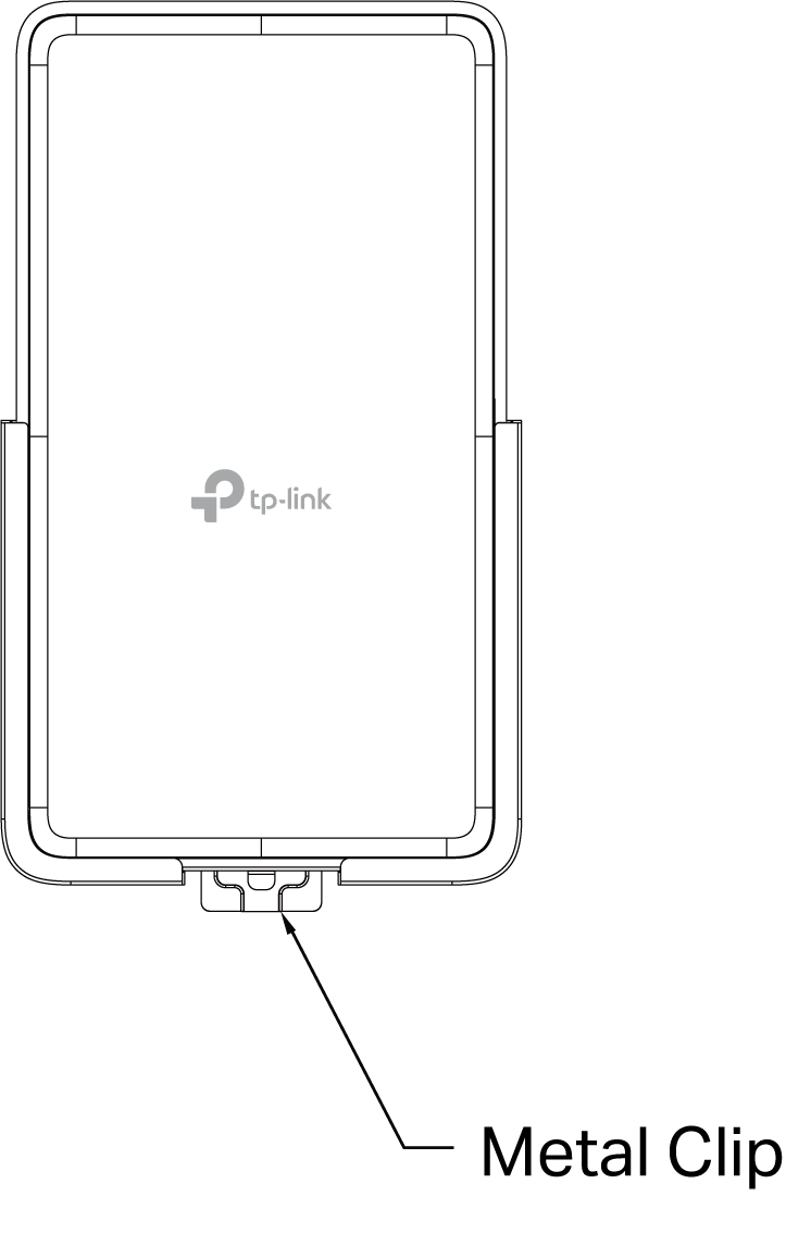
Tips for Window Mounting:
• Avoid air bubbles by applying enough pressure for at least 30 seconds.
• It is recommended that mounting on a window not be done on a wet or rainy day.
• Ensure that the selected window is clean, smooth and dry (a surface without ice, dust, oil or separating agents is recommended).
• Ideal tape application is accomplished when temperature is 21°C -38°C (70°F-100°F) and the bond is allowed to dwell 72 hours. Initial tape application to surfaces at temperatures below 10°C (50°F ) is not recommended.
3. Setup Your Outdoor Router
Method 1: Via the TP-Link Tether App
1. Launch the Apple App Store or Google Play Store and search TP-Link Tether or simply click the button below to download and install the app.


2. Launch the Tether app and log in with your TP-Link ID.
Note: If you don’t have a TP-Link ID, create one first.
3. Tap the + icon on the upper-right corner and select Add a Router. Follow app instructions to set up and connect to the internet.
Method 2: Via the Web Browser
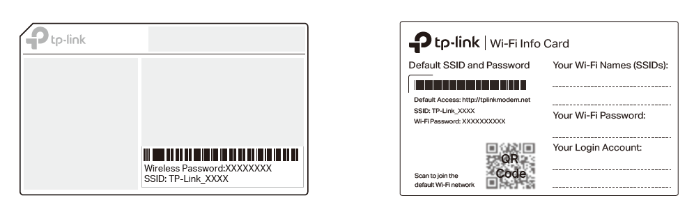
1. Connect your computer to the router wirelessly or via an Ethernet cable. The default wireless name (SSID) and password are printed on the label at the back of the router.
Note: You can also find the default SSID and wireless password on the provided Wi-Fi info card. If you change the password or SSID, it’s recommended to write the new details on the Wi-Fi info card for future reference.
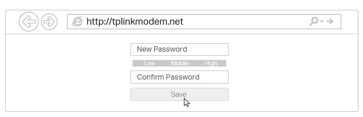
2. Launch a web browser and type in http://tplinkmodem.net or http://192.168.254.1. Create a new password for future logins.
Note: If the login page does not appear, please refer to Q1 of FAQ in this guide.
3. Follow the step-by-step instructions of the Quick Setup to complete the initial configuration.
FAQ
Q1. What should I do if I cannot access the web management page?
• If the computer is set to a static IP address, change its settings to obtain an IP address automatically.
• Make sure http://tplinkmodem.net or http://192.168.254.1 is correctly entered in the web browser.
• Use another web browser and try again.
• Reboot your router and try again.
• Disable and enable the active network adapter in use.
Q2. What should I do if I cannot access the internet?
• Verify that your SIM card is a 5G/4G or WCDMA card.
• Verify that your SIM card is in your internet service provider’s service area.
• Verify that your SIM card has sufficient credit.
• Check the LAN connection: Open a web browser and enter http://tplinkmodem.net or http://192.168.254.1 in the address bar. If the login page does not appear, refer to Q1 and then try again.
• Launch a web browser, log in to the web management page, and check the following:
1) Go to Advanced > Network > Mobile WAN to verify the parameters provided by your ISP are correctly entered. If the parameters are incorrect, click Create Profile and enter the correct parameters, then select the new profile from the Profile Name list.
2) Go to Advanced > Network > PIN Management to verify if PIN is required. If it is, enter the correct PIN provided by your ISP, and click Save.
3) Go to Advanced > Network > Data Settings to verify if the Total/Monthly Used exceeds the Total/Monthly Allowance. If it does, click Correct and set Total/Monthly Used to 0 (zero), or disable Data Limit.
4) Go to Advanced > Network > Mobile WAN to verify that Mobile Data is enabled. If it is not, enable it to access the internet.
5) Confirm with your ISP if you are in a roaming service area. If you are, go to Advanced > Network > Mobile WAN to enable Data Roaming.
Q3. How do I restore the router to its factory default settings?
• With the router powered on, press and hold the Reset button on the bottom panel of the router until the Power LED starts flashing, then release the button. Wait while the router resets.
• Log in to the web management page of the router, and go to Advanced > System Tools > Backup & Restore, click Factory Restore and wait until the reset process is complete.
Q4. What should I do if I forget my web management page password?
• If you are using a TP-Link ID to log in, click Forgot password on the login page and then follow the instructions to reset it.
• Alternatively, refer to Q3 to reset the router, then create a new password to log in.
Q5. What should I do if I forget my wireless network password?
• The default wireless password is printed on the product label of the router.
• If the default wireless password has been changed, log in to the router's web management page and retrieve or reset your password.
Authentication
CE Mark Warning

Power Adapter:
|
Manufacturer |
Model |
Model |
|---|---|---|
|
TP-Link |
CE |
T480050-2-POE |
OPERATING FREQUENCY (the maximum transmitted power)
2400MHz~2483.5MHz (20dBm)
5150MHz~5250MHz (23dBm)
5250MHz~5350MHz (23dBm)
5470MHz~5725MHz (30dBm)
5G N1,3,7,8,20,28,38 (23 dBm ±2.7 dB)
5G N40 (26 dBm +2/-3 dB)
5G N41/77/78 (29 dBm +2/-3 dB)
LTE Band1,3,7,8,20,28,38,40 (23 dBm ±2.7 dB)
LTE Band 41,42,43 (26 dBm +2/-3 dB)
WCDMA Band 1,5,8 (23 dBm ±2 dB)
Frequency band: 5150 - 5250 MHz:
Indoor use: Inside buildings only. Installations and use inside road vehicles and train carriages are not permitted. Limited outdoor use: If used outdoors, equipment shall not be attached to a fixed installation or to the external body of road vehicles, a fixed infrastructure or a fixed outdoor antenna. Use by unmanned aircraft systems (UAS) is limited to within the 5170 - 5250 MHz band.
Frequency band: 5250 - 5350 MHz:
Indoor use: Inside buildings only. Installations and use in road vehicles, trains and aircraft are not permitted. Outdoor use is not permitted.
Frequency band: 5470 - 5725 MHz:
Installations and use in road vehicles, trains and aircraft and use for unmanned aircraft systems (UAS) are not permitted.
EU Declaration of Conformity
TP-Link hereby declares that the device is in compliance with the essential requirements and other relevant provisions of directives 2014/53/EU, 2009/125/EC, 2011 /65/EU and (EU) 2015/863.
The original EU Declaration of Conformity may be found at https://www.tp-link.com/en/support/ce/
RF Exposure Information
This device meets the EU requirements (2014/53/EU Article 3.1a) on the limitation of exposure of the general public to electromagnetic fields by way of health protection.
The device complies with RF specifications when the device used at 37 cm from your body.
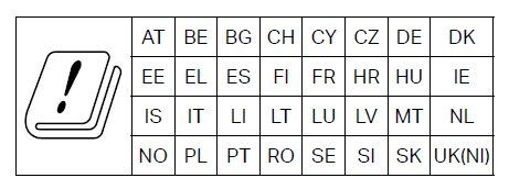
National Restrictions
UKCA Mark

UK Declaration of Conformity
TP-Link hereby declares that the device is in compliance with the essential requirements and other relevant provisions of the Radio Equipment Regulations 2017.
The original UK Declaration of Conformity may be found at https://www.tp-link.com/support/ukca/
National Restrictions
Attention: This device may only be used indoors in Great Britain.
Korea Warning Statements:
당해 무선설비는 운용중 전파혼신 가능성이 있음.

NCC Notice & BSMI Notice
注意!
取得審驗證明之低功率射頻器材,非經核准,公司、商號或使用者均不得擅自變更頻率、加大功率或變更原設計之特性及功能。
低功率射頻器材之使用不得影響飛航安全及干擾合法通信;經發現有干擾現象時,應立即停用,並改善至無干擾時方得繼續使用。
前述合法通信,指依電信管理法規定作業之無線電通信。
低功率射頻器材須忍受合法通信或工業、科學及醫療用電波輻射性電機設備之干擾。
應避免影響附近雷達系統之操作。
高增益指向性天線只得應用於固定式點對點系統。
減少電磁波影響,請妥適使用。
電波功率密度MPE標準值 : XX mW/cm²,送測產品實測值 : XX mW/cm²,建議使用時設備天線至少距離人體20公分。
安全諮詢及注意事項
-
請使用原裝電源供應器或只能按照本產品注明的電源類型使用本產品。
-
清潔本產品之前請先拔掉電源線。請勿使用液體、噴霧清潔劑或濕布進行清潔。
-
注意防潮,請勿將水或其他液體潑灑到本產品上。
-
插槽與開口供通風使用,以確保本產品的操作可靠並防止過熱,請勿堵塞或覆蓋開口。
-
請勿將本產品置放於靠近熱源的地方。除非有正常的通風,否則不可放在密閉位置中。
-
不要私自拆開機殼或自行維修,如產品有故障請與原廠或代理商聯繫。
-
電源供應器应使用在环境温度低於或等於40℃的室內。
限用物質含有情況標示聲明書
| 設備名稱:5G AX3000 Wi-Fi 6 Outdoor Router 型號(型式):Archer NX500-Outdoor Equipment name Type designation (Type) |
||||||
|---|---|---|---|---|---|---|
| 單元 Unit |
限用物質及其化學符號 Restricted substances and its chemical symbols |
|||||
| 鉛 Lead (Pb) |
汞 Mercury (Hg) |
鎘 Cadmium (Cd) |
六價鉻 Hexavalent chromium (Cr+6) |
多溴聯苯 Polybrominated biphenyls (PBB) |
多溴二苯醚 Polybrominated diphenyl ethers (PBDE) |
|
| PCB | ○ | ○ | ○ | ○ | ○ | ○ |
| 外殼 | ○ | ○ | ○ | ○ | ○ | ○ |
| 電源供應器 | − | ○ | ○ | ○ | ○ | ○ |
| 其他及其配件 | − | ○ | ○ | ○ | ○ | ○ |
| 備考1.〝超出0.1 wt %〞及〝超出0.01 wt %〞係指限用物質之百分比含量超出百分比含量基準值 Note 1:“Exceeding 0.1 wt %” and “exceeding 0.01 wt %” indicate that the percentage content of the restricted substance exceeds the reference percentage value of presence condition. 備考2.〝○〞係指該項限用物質之百分比含量未超出百分比含量基準值。 Note 2:“○” indicates that the percentage content of the restricted substance does not exceed the percentage of reference value of presence. 備考3.〝-〞係指該項限用物質為排除項目。 Note 3:The “−” indicates that the restricted substance corresponds to the exemption. |
||||||

Продукт сертифіковано згідно с правилами системи УкрСЕПРО на відповідність вимогам нормативних документів та вимогам, що передбачені чинними законодавчими актами України.

Safety Information
-
Keep the device away from fire or hot environments. DO NOT immerse in water or any other liquid.
-
Do not attempt to disassemble, repair, or modify the device. If you need service, please contact us.
-
Do not use the device where wireless devices are not allowed.
-
Do not use damaged charger or USB cable to charge the device.
-
Do not use any other chargers than those recommended.
-
Adapter should be used indoors where the ambient temperature is lower than or equal to 40°C.
-
Adapter shall be installed near the equipment and shall be easily accessible.
-
The outdoor router can be used either indoors or outdoors.
-
Before mounting your router outdoors, waterproof it to ensure device safety and performance.
-
The waterproof cover must be secured before use!
-
The product can only be installed by instructed person or skilled person!
-
The plug on the power supply cord is used as the disconnect device, the socket-outlet shall be easily accessible.
-
Use only power supplies which are provided by manufacturer and in the original packing of this product. If you have any questions, please don’t hesitate to contact us.
-
This product can be wall-mounted or window-mounted, and the PoE adapter can be wall-mounted. The installation Max. height is no more than 2m.
-
Operating Temperature: -30°C-60°C (-22°F-140°F). Operating Humidity: 5%-95%RH, Non-condensing.
-
Plug the adapter into the wall outlets with earthing connection through the power cord plug.
-
請勿使用損壞的充電器或USB線來供應設備充電。
-
請勿使用推薦充電器以外的任何其他充電器。
-
變壓器應安裝在設備附近且易於操作。
-
運作溫度: -30°C-60°C (-22°F-140°F)
-
This product uses radios and other components that emit electromagnetic fields. Electromagnetic fields and magnets may interfere with pacemakers and other implanted medical devices. Always keep the product and its power adapter more than 15 cm (6 inches) away from any pacemakers or other implanted medical devices. If you suspect your product is interfering with your pacemaker or any other implanted medical device, turn off your product and consult your physician for information specific to your medical device.
Please read and follow the above safety information when operating the device. We cannot guarantee that no accidents or damage will occur due to improper use of the device. Please use this product with care and operate at your own risk.
ERP Information
Power consumption in networked standby: 5.96 W
Power consumption in networked standby when all wired network ports are connected and all wireless network ports are activated: 8.26 W.
The default period of time after which the power management function switches the equipment automatically into a condition providing networked standby: 20 minutes
How to activate and deactivate wireless network: Enter the webpage of product through wired connecting. The wireless function can be turn on/off via Basic- ->Wireless - -> Enable/Disable Wireless Checkbox.
Explanation of the symbols on the product label
The product label is on the bottom of the product and its power supply. Symbols may vary from products.
| Symbol 符號解釋 |
Explanation 解釋 |
|---|---|
 |
Class II equipment II类设备 |
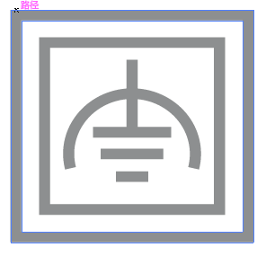 |
Class II equipment with functional earthing 具有功能接地的II类设备 |
 |
Alternating current 交流電 |
 |
DC voltage 直流電壓 |
 |
Polarity of output terminals 輸出端子極性 |
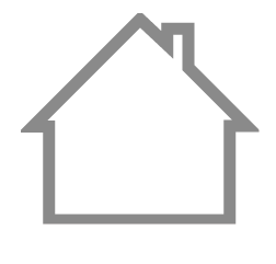 |
Indoor use only 僅限室內使用 |
 |
Dangerous voltage 危險電壓 |
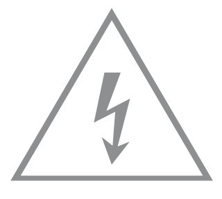 |
Caution, risk of electric shock 注意,有觸電危險 |
 |
Energy efficiency Marking 能源效率標示 |
 |
Protective earth 保護接地 |
 |
Earth 接地 |
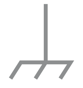 |
Frame or chassis 機架接地 |
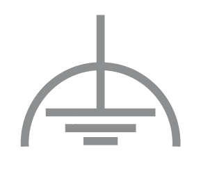 |
Functional earthing 功能接地 |
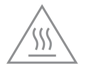 |
Caution, hot surface 警告,表面高溫 |
 |
Caution 警告 |
 |
Operator’s manual 操作手冊 |
 |
Stand-by 待機 |
 |
“ON”/”OFF” (push-push) 「開」/「關」 ( 按壓式) |
 |
Fuse 保險絲 |
 |
Fuse is used in neutral N 保險絲用於中性線N |
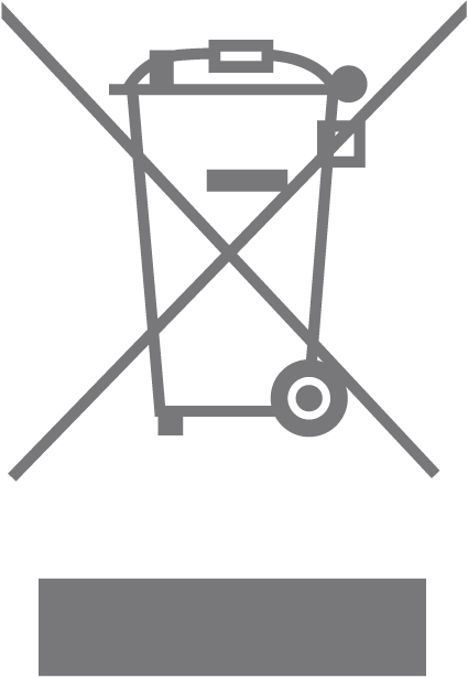 |
RECYCLING This product bears the selective sorting symbol for Waste electrical and electronic equipment (WEEE). This means that this product must be handled pursuant to European directive 2012/19/EU in order to be recycled or dismantled to minimize its impact on the environment. User has the choice to give his product to a competent recycling organization or to the retailer when he buys a new electrical or electronic equipment. 回收利用 本產品標示有「廢棄電氣電子設備(WEEE)」的分類回收標誌。這表示本產品必須依據歐盟指令 2012/19/EU 進行妥善回收或拆 解,以減少對環境的影響。 使用者可選擇將本產品交給合格的回收機構,或在購買新電器或電子設備時,交回給零售商進行回收處理。 |
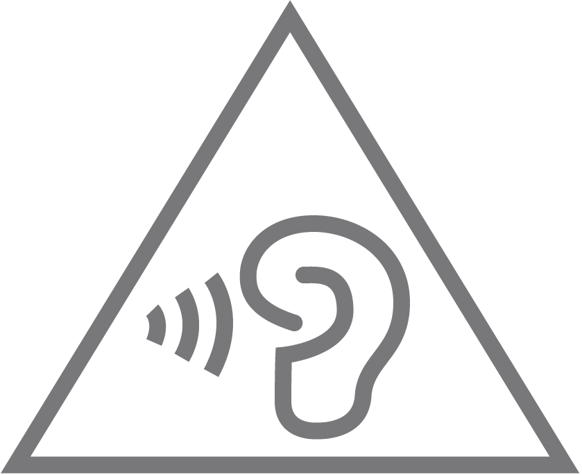 |
Caution, avoid listening at high volume levels for long periods 注意,避免長時間以高音量收聽 |
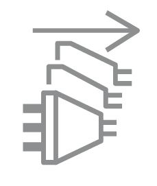 |
Disconnection, all power plugs 斷開所有電源插頭 |
| m | Switch of mini-gap construction 微間隙結構的開關 |
| µ | Switch of micro-gap construction (for US version) Switch of micro-gap / micro-disconnection construction (for other versions except US) 微小間隙結構開關(適用於美國版) 微小間隙 / 微小斷開結構開關(適用於美國以外的其他版本) |
| ε | Switch without contact gap (Semiconductor switching device) 無接點間隙開關(半導體開關裝置) |